Personal and expert advice
25 years of experience
Fast delivery times
Competitive prices

Dry Aviation Couplings
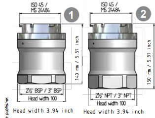
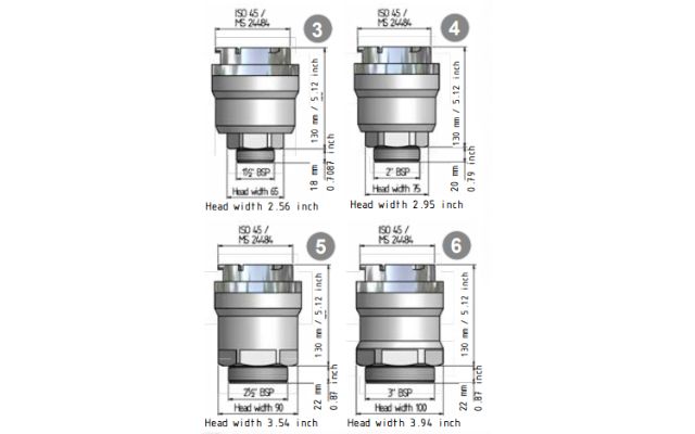
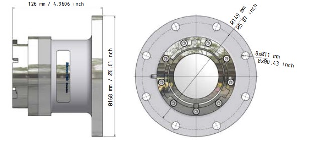
The Dry Aviation Couplings are designed for use in aviation and military refuelling systems with a maximum working pressure of 10 bar (150 psi). Working temperature range lies within -38o C (-36o F) to +60o C (+140o F),observe that special low temperature seals are used in cold environments. This coupling is not configured for under wing refuelling.
All units can also be used as bottom loading or primary points refuelling vehicles. All units are manufactured to accept the international standard: 2½" the point bayonet, hose end refuelling nozzles, according to: ISO 45 / MS24484 / NATO STANAG 3105 / British Aerospace Specification 2C14.
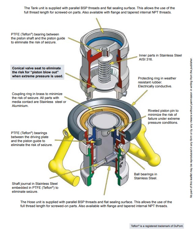
The couplings consist of high strength aluminium body, coupling ring in gunmetal andbayonet flange and inner parts in stainless
steel and aluminium.
All wetted parts in aluminium and stainless steel.

ISO 45, MS24484, NATO STANAG 3105, British Aerospace Specification 2C14
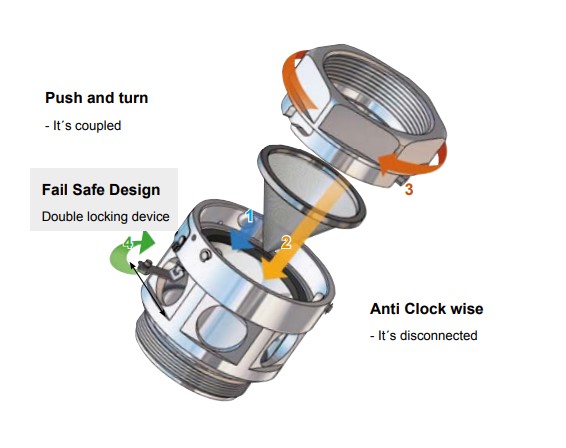
The DACouplings include a bayonet-type connector and are flanged or threaded to suit installation requirements. Each tank unit contains a “fail safe” springloaded valve seating on a tapered seat. The valve is controlled by the action of coupling and uncoupling the hose unit.
Selective units are fitted with setting rings. These have slots cut into them to match up with the corresponding pins on the selective sleeve on the hose unit.
Care must be taken when reassembling such units to ensure that the ring is returned to its original position.
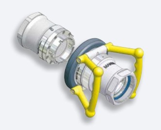
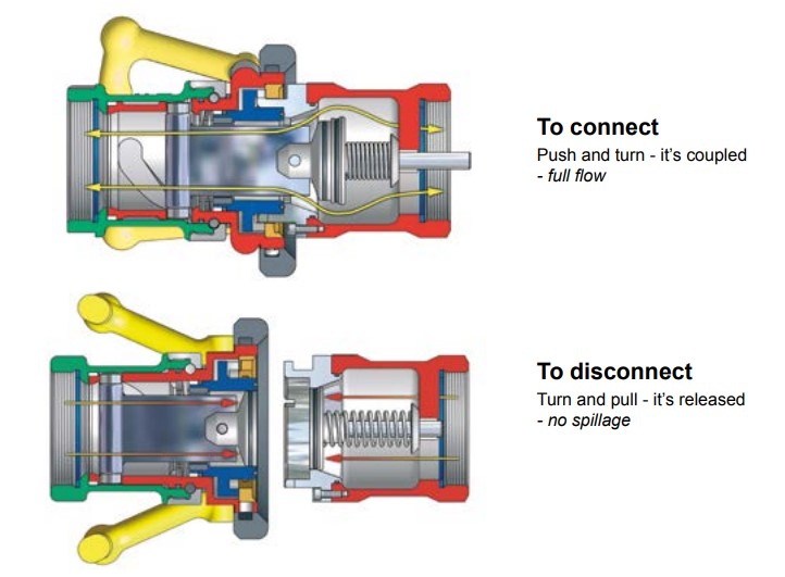
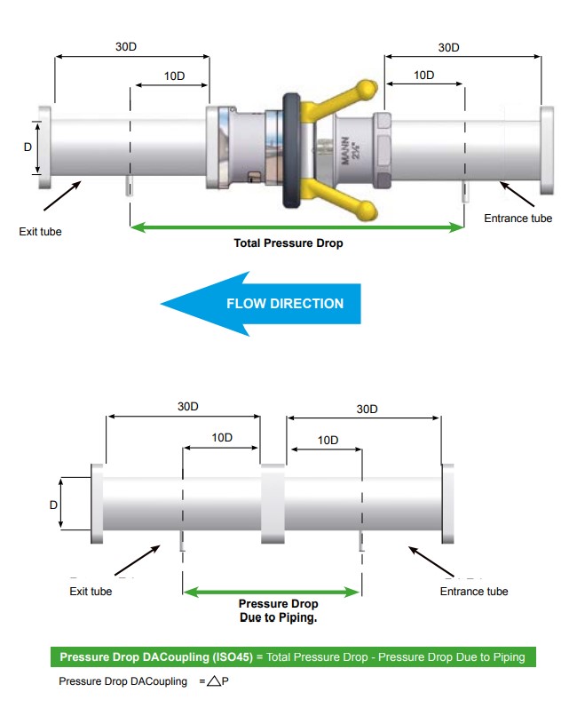
Illustration Pressure Drop Measurement
According to NATO STANAG 3756, Annex E
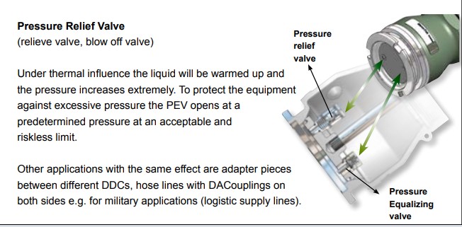
Pressure equalizing valve in ISO 45 Tank unit and STANAG 3756 Tank unit
This system dissipates trapped fluid pressure into hose coupler without spillage, to allow easy connection.
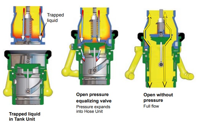
No yellow parts (Brass and Bronze) in contact with the fuel.
| Threads: |
| BSP = ISO 228 |
| NPT = B1.20.1 |
|
Connection |
Length |
Head width |
Weight |
Code No |
|
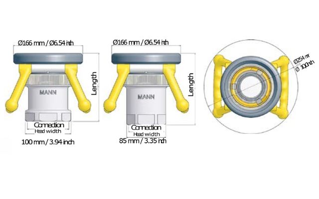
2½" BSP |
64 mm/6.46 inch |
85 mm / 3.35 inch |
3.4 kg / 7.5 lbs |
F312B1101B |
|
3" BSP |
164 mm/6.46 inch |
100 mm / 3.94 inch |
3.5 kg / 7.7 lbs |
F314B1101B |
|
2½" NPT |
172 mm/6.77 inch |
85 mm / 3.35 inch |
3.4 kg / 7.5 lbs |
F313B1101 |
|
3" NPT |
174 mm/6.85 inch |
100 mm / 3.94 inch |
3.5 kg / 7.7 lbs |
F315B1101 |
We make specials. Other materials, connection and sealings on request.
|
Flange1) |
Material |
Seal O-ring |
Code No |
|
|
undrilled Ø210 mm |
|
|
F320B1101 |
|
|
DN 65 PN 10/16 Type A |
|
|
F333B1101 |
|
|
DN 80 PN 10/16 Type A |
|
Standard |
F336B1101 |
|
|
2½" ASA 150 psi |
F359B1101 |
|||
|
Al |
FPM/KFM (Viton®) |
|||
|
3" ASA 150 psi |
F361B1101 |
|||
|
TW1 (DN80) |
|
Other on |
F365B1101 |
|
|
|
request |
|||
|
TW3 (DN100) |
F366B1101 |
|||
|
3" TTMA |
|
|
F367B1101 |
|
|
4" TTMA |
|
|
F368B1101 |
1) Flanges according to EN 1092 , ANSI 5 and DIN 28459.
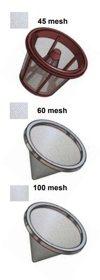
The Filter Strainer is designed to adapt on the DACoupling according to the ISO45 standard. The integrated view glass makes it easy to check when the filter has to be cleaned. Easy servicing is guaranteed by a new bayonet connection.
The Filter Strainers are available with 2½" BSP/NPT and 3" BSP/NPT connections.
Sight flow indicator with male BSP thread screws into a ISO 45 Hose Unit / Coupler with female threads.
There are 3 different filter types, 45 mesh, 60 mesh and 100 mesh. When order replace XX with -45 for 45 mesh, -60 for 60 mesh and -10 for 100 mesh.
Standard connections:
|
Size |
End connection (female) |
HU connection (male) |
|
U1280S1101-XX |
2½" BSP |
2½" BSP |
|
U1281S1101-XX |
2½" BSP |
2½" NPT |
|
U1380S1101-XX |
2½" NPT |
2½" BSP |
|
U1381S1101-XX |
2½" NPT |
2½" NPT |
|
U1482S1101-XX |
3" BSP |
3" BSP |
|
U1483S1101-XX |
3" BSP |
3" NPT |
|
U1582S1101-XX U1583S1101-XX |
3" NPT 3" NPT |
3" BSP 3" NPT |
Other combinations or connections on request.
Electrostatic charges can be generated by a varietyof circumstances. Ignition of flammable vapoursis possible by discharge of static.
Electrical conductive hoses and anti-static additives reduces the risk but might not be sufficient. Than the aircraft, the fuelling vehicle, and all accessories including hose nozzle, filters and other equipment through which the fuel passes must all be electrically bonded.
Such connections must always be attached to appropriate bonding connections thus pro viding a conductive path to equalize potential.
Removal of the bonding connection must always be the last operation.
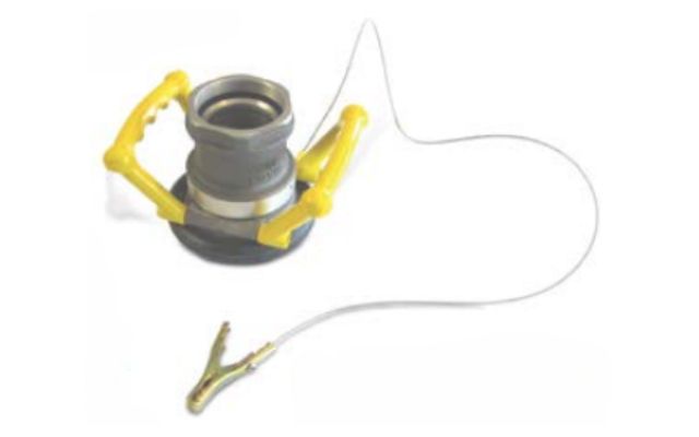
Ground cable assembly with solid brass clamp and bold. Cable with plastic coating.
Body material in aluminium and stainless steel.
|
Connection |
Mate- rial |
Weight |
Code No |
|
2½" BSP |
AL |
2.3 kg / 5.1 lbs |
G312A1401B |
|
3" BSP |
2.3 kg / 5.1 lbs |
G314A1401B |
|
|
2½" NPT |
2.3 kg / 5.1 lbs |
G313A1401B |
|
|
3" NPT |
2.3 kg / 5.1 lbs |
G315A1401B |
|
|
2½" BSP |
SS |
- |
G312A4401B |
|
3" BSP |
- |
G314A4401B |
|
|
2½" NPT |
- |
G313A4401B |
|
|
3" NPT |
- |
G315A4401B |
| Working pressure: | test pressure: |
| 10 bar / 150 psi | 15 bar / 225 psi |
| Threads: | |
| BSP = ISO 228, | NPT = B1.20.1 |
Body material in aluminium and stainless steel.
|
Connection |
Mate- rial |
Weight |
Code No |
|
1½" BSP |
AL |
2.1 kg / 4.6 lbs |
G375A1401B |
|
2" BSP |
2.2 kg / 4.8 lbs |
G378A1401B |
|
|
2½" BSP |
2.2 kg / 4.8 lbs |
G380A1401B |
|
|
3" BSP |
2.3 kg / 5.1 lbs |
G382A1401B |
|
|
1½" BSP |
SS |
- |
G375A4401B |
|
2" BSP |
- |
G378A4401B |
|
|
2½" BSP |
- |
G380A4401B |
|
|
3" BSP |
- |
G382A4401B |
| Working pressure: | Test pressure: |
| 10 bar / 150 psi | 15 bar / 225 psi |
| Threads: | |
| BSP = ISO 228, | NPT = B1.20.1 |
Body material in aluminium and stainless steel.
|
Flange |
Material (Body) |
Weight |
Code No |
|
2½" ASA 150 psi |
AL |
2.7 kg / 6.0 lbs |
G359D1401 |
|
2½" ASA 150 psi |
SS |
- |
G359B4401 |
Body material in aluminium and stainless steel.
|
Flange |
Material (Body) |
Weight |
Code No |
|
3" ASA 150 psi |
AL |
2.9 kg / 6.4 lbs |
G361D1401 |
|
3" ASA 150 psi |
SS |
- |
G361B4401 |
Body material in aluminium and stainless steel.
|
Flange |
Material (Body) |
Weight |
Code No |
|
DN 65 PN 10/16 |
AL |
2.8 kg 6.2 lbs |
G333D1401 |
|
DN 65 PN 10/16 |
SS |
- |
G333B4401 |
Body material in aluminium and stainless steel.
|
Flange |
Material (Body) |
Weight |
Code No |
|
DN 80 PN 10/16 |
AL |
3.0 kg / 6.6 lbs |
G336D1401 |
|
DN 80 PN 10/16 |
SS |
- |
G336B4401 |
Body material in aluminium and stainless steel.
|
Flange |
Material (Body) |
Weight |
Code No |
|
TW1 (DIN 28459) |
AL |
2.5 kg / 5.5 lbs |
G365D1401 |
|
TW1 (DIN 28459) |
SS |
- |
G365B4401 |
Body material in aluminium and stainless steel.
|
Flange |
Material (Body) |
Weight |
Code No |
|
TW3 (DIN 28459) |
AL |
2.9 kg / 6.4 lbs |
G366D1401 |
|
TW3 (DIN 28459) |
SS |
- |
G366B4401 |
Body material in aluminium and stainless steel.
|
Flange |
Material (Body) |
Weight |
Code No |
|
3" TTMA |
AL |
2.4 kg / 5.3 lbs |
G367D1401 |
|
3" TTMA |
SS |
- |
G367B4401 |
Body material in aluminium and stainless steel.
|
Flange |
Material (Body) |
Weight |
Code No |
|
4" TTMA |
AL |
2.6 kg / 5.7 lbs |
G368D1401 |
|
4" TTMA |
SS |
- |
G368B4401 |
Body material in aluminium and stainless steel.
|
Flange |
Material (Body) |
Weight |
Code No |
|
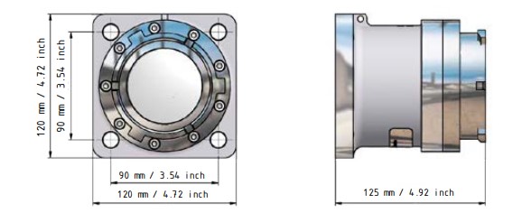
Square flange, 120 mm / 4.72 inch |
AL |
2.7 kg / 6.0 lbs |
G3107D1401 |
|
Square flange, 120 mm / 4.72 inch |
SS |
- |
G3107B4401 |
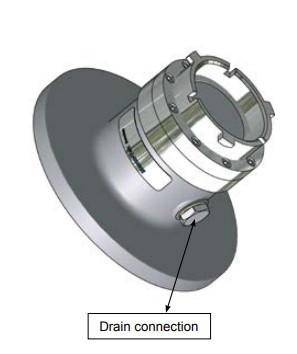
Option Drain connection
Use Mann-Tek ISO45 with Drain connection for easy draining and sampling of your system.
Available in all Tank units with flange
Drain connection: 3/8" ( thread standard)
Other threads on request.
How to Order: Code nr. + D-G3-11-C1
|
Code nr: |
Material: |
Weight: |
|
K300A1101 |
Aluminium |
0,5 kg / 1.10 lbs |
|
K300A2201 |
Composite1) |
0.2 kg / 0,44 lbs |
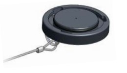
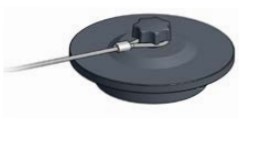
A dust cap should be used to prevent the ingress of dirt or water.
Dust Cap (for Tank Unit)
|
Code nr: |
Material: |
Weight: |
|
I300A1101 |
Aluminium |
0,4 kg / 0.88 lbs |
|
I300A2201 |
Composite1) |
0.2 kg / 0.44 lbs |
A dust cap should be used to prevent the ingress of dirt or water.
Dust Plug (for HoseUnit)
Size of ISO45 DACoupling: 2½" (DN 65)
Materials: Aluminium
Seals: FPM (Viton*) or NBR (Nitrile) , Low temperature NBR, FQM (Flourosilicon)
*) Viton is a registered trademark of DuPoint
Lowest Operation Temperature:
| With seals material: | Lowest temperature: |
| FPM (standard Viton) |
-20º C / -4º F |
| NBR | -25º C / -13º F |
| Low temperature NBR |
-40º C / -40º F |
| FQM (Flourosiliconen) | -55º C / -67º F |
These materials must be tried indvidually and are subject to no obligation. Always check with chemical compability chart before use.
Max Working Pressure: 10 bar (150 psi)
Test Pressure: 15 bar (225 psi)
Min. Burst Pressure: 50 bar (750 psi)
Safety Factor: 5:1
End Connections: BSP- and NPT-threads, DIN- and ASA-flanges. Other connections on request.
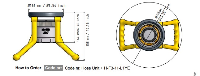
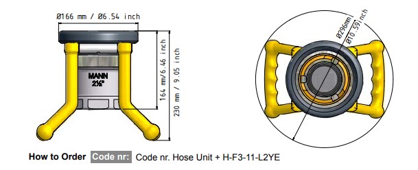
 2½" ISO45 Hose Unit to Tank Unit 3" (119 mm)1) STANAG 3756
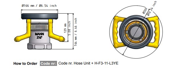
 3" (119 mm)1) Tank Unit STANAG 3756 to 2½" (105 mm)1) Hose unit
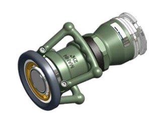
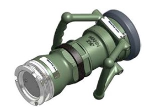
The ISO45 coupling, in green colour, are also used for
Military purposes with different adaptor systems.
Connection adaptor:
• 2½" ISO45 to 3" (119 mm)1) Tank Unit STANAG 3756.
• 2½" ISO45 to 3" (119 mm)1) TW EN14420-5
• 3" (119 mm)1) Hose Unit / Tank Unit STANAG 3756
to 3" (119 mm)1) TW EN14420- 5 Hose Unit / Tank Unit
• 3" (119 mm)1) Tank Unit STANAG 3756
to 2½" (105 mm)1) Hose Unit
The ISO45 Tank Unit are also available with pressure
equalizing valve and pressure relief valve.
1) Connection 119 mm = 4.68 inch and 105 mm = 4.13 inch
Examples of Military RAL colours
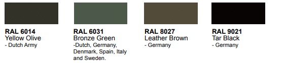
Other colours on request
We can not quarantee that the colours above are correctly illustrated because print quality
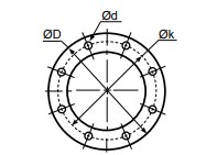
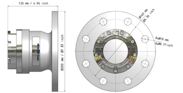
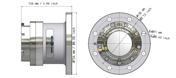
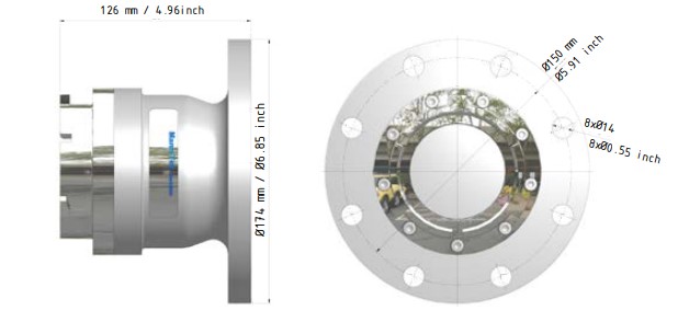
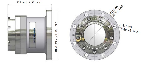
Ø D = Diameter
Ø k = Centre diameter
n = Numer of holes
Ø d = Hole diameter
|
EN 1092-1 |
|
DN |
PN 10 |
PN 16 |
PN 25 |
PN 40 |
||||||||||||
|
ØD |
Øk |
n |
Ød |
ØD |
Øk |
n |
Ød |
ØD |
Øk |
n |
Ød |
ØD |
Øk |
n |
Ød |
|
|
20 |
mm 105 |
75 |
4 |
14 |
105 |
75 |
4 |
14 |
105 |
75 |
4 |
14 |
105 |
75 |
4 |
14 |
|
|
inch 4.13 |
2.95 |
0.55 |
4.13 |
2.95 |
0.55 |
4.13 |
2.95 |
0.55 |
4.13 |
2.95 |
0.55 |
||||||
|
25 |
mm |
115 |
85 |
4 |
14 |
115 |
85 |
4 |
14 |
115 |
85 |
4 |
14 |
115 |
85 |
4 |
14 |
|
inch |
4.53 |
3.35 |
0.55 |
4.53 |
3.35 |
0.55 |
4.53 |
3.35 |
0.55 |
4.53 |
3.35 |
0.55 |
|||||
|
32 |
mm |
140 |
100 |
4 |
18 |
140 |
100 |
4 |
18 |
140 |
100 |
4 |
18 |
140 |
100 |
4 |
18 |
|
inch |
5.51 |
3.94 |
0.71 |
5.51 |
3.94 |
0.71 |
5.51 |
3.94 |
0.71 |
5.51 |
3.94 |
0.71 |
|||||
|
40 |
mm |
150 |
110 |
4 |
18 |
150 |
110 |
4 |
18 |
150 |
110 |
4 |
18 |
150 |
110 |
4 |
18 |
|
inch |
5.91 |
4.33 |
0.71 |
5.91 |
4.33 |
0.71 |
5.91 |
4.33 |
0.71 |
5.91 |
4.33 |
0.71 |
|||||
|
50 |
mm |
165 |
125 |
4 |
18 |
165 |
125 |
4 |
18 |
165 |
125 |
4 |
18 |
165 |
125 |
4 |
18 |
|
inch |
6.50 |
4.92 |
0.71 |
6.50 |
4.92 |
0.71 |
6.50 |
4.92 |
0.71 |
6.50 |
4.92 |
0.71 |
|||||
|
65 |
mm |
185 |
145 |
4 |
18 |
185 |
145 |
4 |
18 |
185 |
145 |
8 |
18 |
185 |
145 |
8 |
18 |
|
inch |
7.28 |
5.71 |
0.71 |
7.28 |
5.71 |
0.71 |
7.28 |
5.71 |
0.71 |
7.28 |
5.71 |
0.71 |
|||||
|
80 |
mm |
200 |
160 |
8 |
18 |
200 |
160 |
8 |
18 |
200 |
160 |
8 |
18 |
200 |
160 |
8 |
18 |
|
inch |
7.87 |
6.30 |
0.71 |
7.87 |
6.30 |
0.71 |
7.87 |
6.30 |
0.71 |
7.87 |
6.30 |
0.71 |
|||||
|
100 |
mm |
220 |
180 |
8 |
18 |
220 |
180 |
8 |
18 |
235 |
190 |
8 |
22 |
235 |
190 |
8 |
22 |
|
inch |
8.66 |
7.09 |
0.71 |
8.66 |
7.09 |
0.71 |
9.25 |
7.48 |
0.87 |
9.25 |
7.48 |
0.87 |
|||||
|
125 |
mm |
250 |
210 |
8 |
18 |
250 |
210 |
8 |
18 |
270 |
220 |
8 |
26 |
270 |
220 |
8 |
26 |
|
inch |
9.84 |
8.27 |
0.71 |
9.84 |
8.27 |
0.71 |
10.63 |
8.66 |
1.02 |
10.63 |
8.66 |
1.02 |
|||||
|
150 |
mm |
285 |
240 |
8 |
22 |
285 |
240 |
8 |
22 |
300 |
250 |
8 |
26 |
300 |
250 |
8 |
26 |
|
inch |
11.22 |
9.45 |
0.87 |
11.22 |
9.45 |
0.87 |
11.81 |
9.84 |
1.02 |
11.81 |
9.84 |
1.02 |
|||||
|
200 |
mm |
340 |
295 |
8 |
22 |
340 |
295 |
12 |
22 |
360 |
310 |
12 |
26 |
375 |
320 |
12 |
30 |
|
inch |
13.39 |
11.61 |
0.87 |
13.39 |
11.61 |
0.87 |
14.17 |
12.20 |
1.02 |
14.76 |
12.60 |
1.18 |
|||||
|
250 |
mm |
395 |
355 |
12 |
22 |
405 |
355 |
12 |
26 |
425 |
370 |
12 |
30 |
450 |
385 |
12 |
33 |
|
inch |
15.55 |
13.98 |
0.87 |
15.94 |
13.98 |
1.02 |
16.73 |
14.57 |
1.18 |
17.72 |
15.16 |
1.30 |
|||||
|
300 |
mm |
445 |
400 |
12 |
22 |
460 |
410 |
12 |
26 |
485 |
430 |
16 |
30 |
515 |
450 |
16 |
33 |
|
inch |
17.52 |
15.75 |
0.87 |
18.11 |
16.14 |
1.02 |
19.09 |
16.93 |
1.18 |
20.28 |
17.65 |
1.30 |
|||||
Flange translation EN 1092----- DIN
|
EN 1092-1 EN 1092-1 PN 6 |
DIN. |
|
DIN 2631 |
|
|
EN 1092-1 PN 10 |
DIN 2632 |
|
EN 1092-1 PN 16 |
DIN 2633 |
|
EN 1092-1 PN 25 |
DIN 2634 |
|
EN 1092-1 PN 40 |
DIN 2635 |
|
EN 1092-1 Type B Raised Face |
DIN 2526 Form C |
|
EN 1092-1 Type C Tongue |
DIN 2512 Form F |
|
EN 1092-1 Type D Groove |
DIN 2512 Form N |
|
EN 1092-1 Type E Spigot |
DIN 2513 Form V |
|
EN 1092-1 Type F Recess |
DIN 2513 Form R |
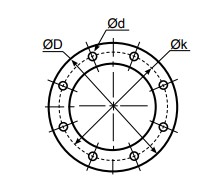
Ø D = Diameter
Ø k = Centre diameter
n = Numer of holes
Ø d = Hole diameter
|
ANSI (ASA) B 16,5 |
|
INCH |
150 psi |
300 psi |
||||||
|
ØD |
Øk |
n |
Ød |
ØD |
Øk |
n |
Ød |
|
|
3/4” |
mm |
98,4 |
69,8 |
4 |
15,9 |
117,5 |
82,5 |
4 |
19 |
|
inch |
3 7/8 |
2 3/4 |
5/8 |
4 5/8 |
3 1/4 |
3/4 |
|||
|
1” |
mm |
107,7 |
79,4 |
4 |
15,9 |
123,8 |
88,9 |
4 |
19 |
|
inch |
4 1/4 |
3 1/8 |
5/8 |
4 7/8 |
3½ |
3/4 |
|||
|
1 1/4” |
mm |
117,5 |
88,9 |
4 |
15,9 |
133,3 |
98,4 |
4 |
19 |
|
inch |
4 5/8 |
3½ |
5/8 |
5 1/4 |
3 7/8 |
3/4 |
|||
|
1 1/2” |
mm |
127 |
98,4 |
4 |
15,9 |
155,6 |
114,3 |
4 |
22,2 |
|
inch |
5 |
3 7/8 |
5/8 |
6 1/8 |
4½ |
7/8 |
|||
|
2” |
mm |
152,4 |
120,6 |
4 |
19 |
165,1 |
127 |
8 |
19 |
|
inch |
6 |
4 3/4 |
3/4 |
6½ |
5 |
3/4 |
|||
|
2 1/2” |
mm |
177,8 |
139,7 |
4 |
19 |
190,5 |
149,2 |
8 |
22,2 |
|
inch |
7 |
5½ |
3/4 |
7½ |
5 7/8 |
7/8 |
|||
|
3” |
mm |
190,5 |
152,4 |
4 |
19 |
209,5 |
168,3 |
8 |
22,2 |
|
inch |
7½ |
6 |
3/4 |
8 1/4 |
6 5/8 |
7/8 |
|||
|
4” |
mm |
228,5 |
190,5 |
8 |
19 |
254 |
200 |
8 |
22,2 |
|
inch |
9 |
7½ |
3/4 |
10 |
7 7/8 |
7/8 |
|||
|
5” |
mm |
254 |
215,9 |
8 |
22,2 |
279,4 |
234,9 |
8 |
22,2 |
|
inch |
10 |
8½ |
7/8 |
11 |
9 1/4 |
7/8 |
|||
|
6” |
mm |
279,4 |
241,3 |
8 |
22,2 |
317,5 |
269,9 |
12 |
22,2 |
|
inch |
11 |
9½ |
7/8 |
12½ |
10 5/8 |
7/8 |
|||
|
8” |
mm |
342,9 |
298,4 |
8 |
22,2 |
381 |
330,2 |
12 |
25,4 |
|
inch |
13½ |
11 3/4 |
7/8 |
15 |
13 |
1 |
|||
|
10” |
mm |
406,4 |
361,9 |
12 |
25,4 |
444,5 |
387,3 |
16 |
28,6 |
|
inch |
16 |
141/4 |
1 |
17½ |
15 1/4 |
1 1/8 |
|||
|
12” |
mm |
482,6 |
431,8 |
12 |
25,4 |
520,7 |
450,8 |
16 |
31,7 |
|
inch |
19 |
17 |
1 |
20½ |
17 3/4 |
1 1/4 |
|
TW DIN 28459 |
|
|
DN |
ØD |
Øk |
n |
Ød |
|
TW1 |
50 |
mm |
154 |
130 |
8 |
11 |
|
inch |
6.06 |
5.12 |
|
0.43 |
||
|
TW1 |
80 |
mm |
154 |
130 |
8 |
11 |
|
inch |
6.06 |
5.12 |
|
0.43 |
||
|
TW3 |
100 |
mm |
174 |
150 |
8 |
14 |
|
inch |
6.85 |
5.91 |
|
0.55 |
||
|
TW5 |
125 |
mm |
204 |
176 |
8 |
14 |
|
inch |
8.03 |
6.93 |
|
0.55 |
||
|
TW7 |
150 |
mm |
240 |
210 |
12 |
14 |
|
inch |
9.45 |
8.27 |
|
0.55 |
|
T.T.M.A |
|
INCH |
ØD |
Øk |
n |
Ød |
|
2” |
mm |
114,3 |
95,3 |
6 |
11,1 |
|
inch |
4.50 |
3.75 |
0.44 |
||
|
3” |
mm |
142,9 |
123,8 |
8 |
11,1 |
|
inch |
5.63 |
4.87 |
0.44 |
||
|
4” |
mm |
168,3 |
149,2 |
8 |
11,1 |
|
inch |
6.63 |
5.87 |
0.44 |
||
|
5” |
mm |
196,9 |
177,8 |
12 |
11,1 |
|
inch |
7.75 |
7.00 |
0.44 |
||
|
6” |
mm |
228,6 |
206,4 |
12 |
11,1 |
|
inch |
9.00 |
8.13 |
0.44 |
||
|
8” |
mm |
276,2 |
257,2 |
16 |
11,1 |
|
inch |
10.87 |
10.13 |
0.44 |
Mounting instruction
When installing Mann Tek equipment to new pipe work, tanks, etc. ensure the system is free from debris that may be transferred through the coupling. Where the hose or loading arm assembly is the primary static dissipation or earth route, the electrical continuity value of the assembly shall be checked to ensure regulatory compliance. Special attention should be paid to the balancing of loading arms. The weight of the coupling plus transfer media should be taken into account at the specification stage. It is usual for loading arm balance settings to account of weight variations due to differences in the full / empty cycle.
The loading arm should be set to balance in the condition present at the time of connection. For example, should the loading arm be empty at the time of connection then it should be balanced in the empty condition.
The Mann-Tek product can be installed directly in the product line and is ready for use after removing the transport protection. The installation is recommended as follows:
a. Remove the packaging and the flange protection
b. Check the coupling for damages before mounting.
c. To prevent damages during mounting a suitable wrench should be used for the intended bolts and nuts.
d. Ensure that the product line is empty and all valves are close
before you connect the coupling into the line.
e. Set in all bolts first and tighten them by hand. Then increase the tightening torque in 2 steps up to the
recommended value in the following table. Proceed every time according to the sequence shown in g.
f. Tightening torque1) for bolts:
|
Metric |
|
|
Size 8.8 |
|
|
M8 |
24 Nm |
|
M10 |
50 Nm |
|
M12 |
85 Nm |
|
M16 |
210 Nm |
|
M20 |
410 Nm |
|
M22 |
550 Nm |
|
M24 |
700 Nm |
|
Inch Size A193 B7 |
|
|
5/16 -18 UNC |
16 lbf-ft |
|
3/8 -16 UNC |
29 lbf-ft |
|
1/2 -13 UNC |
70 lbf-ft |
|
5/8 -11 UNC |
139 lbf-ft |
|
3/4 -10 UNC |
243 lbf-ft |
|
7/8 -9 UNC |
389 lbf-ft |
|
1 -8 UNC |
582 lbf-ft |
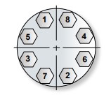
g. Bolt tightening sequence
4 Bolt Pattern 8 Bolt Pattern 12 Bolt Pattern

.jpg)
The start-up may take place only when the Mann-Tek product has been mounted as instructed and the necessary function tests and leak tests have been conducted by the approved authorities.
1) The torque forces recommended bases on a thread friction coefficient μ=0,14 and a standard flat seal
according to EN 1514-1
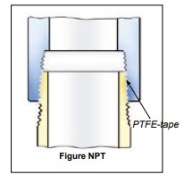
NPT
Sealing NPT threads can be an exasperating experience if certain techniques are not followed. The following tips will help alleviate many common problems in thread sealing:
1. Always use some type of sealant (tape or paste) and apply sealant to male thread only. If using a hydraulic sealant, allow sufficient curing time before system is pressurized.
2. When using tape sealant, wrap the threads in a clock-wise motion starting at the first thread and, as layers are applied, work towards the imperfect (vanishing) thread. If the system that the connection being made to cannot tolerate foreign matter (i.e. air systems), leave the first thread exposed and apply the tape sealant as outlined above.
3. When using paste sealant, apply to threads with a brush, using the brush to work the sealant into the threads. Apply enough sealant to fill in all the threads all the way around.
4. When connecting one stainless steel part to another stainless steel part that will require future disassembly, use a thread sealant that is designed for stainless steel. This stainless steel thread sealant is also useful when connecting aluminium to aluminium that needs to be disconnected in the future. These two materials gall easily, and if the correct sealant is not used, it can be next to impossible to disassemble.
5. When connecting parts made of dissimilar metals (i.e. steel and aluminium), standard tape or paste sealant per forms satisfactory.
6. For sizes 2” and below, tape or paste performs satisfactory. When using thread tape, four wraps (covering all necessary threads) is usually sufficient.
7. For sizes 2½” and above, thread paste is recommended. If thread tape is used, eight wraps (covering all necessary threads) is usually sufficient. Apply more wraps if necessary.
8. For stubborn to seal threads, apply a normal coating of thread paste followed by a normal layer of thread tape.
9. For extremely stubborn to seal threads, apply a normal coating of thread paste followed by a single layer of gauze bandage followed by
a normal layer of thread tap.
Caution!
When this procedure is done, the connection becomes permanent. Extreme measures will be necessary to disconnect these components.
All other measures to seal the threads should be explored prior to use of this technique.
10. Over-tightening threads can be just as detrimental as insufficient tightening. For sizes 2” and below, hand tighten the components and,
with a wrench, tighten 3 full turns. For sizes 2½” and above, hand tighten the components and, with a wrench, tighten 2 full turns.
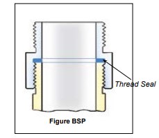
The threads are parallel with flat sealing surface. This allows to use the full thread length for screwed-on parts. The largest possible transfer of force is guaranteed for short length. The thread seal behind the relief groove of the thread cannot drop out.
Simple screwing down, makes a safe connection. Subsequent tightening during operation is possible at any time. Change of seal and new
assembly do not require any expert knowledge.
The European standardisations for hose assemblies require parallel threads with flat seals, because of the advantages.
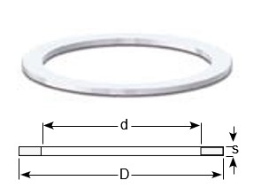
|
weight ≈kg |
Thread BSP |
Materials Application |
Dimensions ≈ mm |
Product No |
||
|
D |
d |
s |
||||
|
0,001 |
BSP 1/2” |
PTFE ( Teflon®) white , massive continuously hard, universally resistant
Teflon® is a registered trademark of DuPont |
20 |
13 |
2 |
On request |
|
0,001 |
BSP 3/4” |
26 |
19 |
2 |
1498-06 |
|
|
0,002 |
BSP 1” |
33 |
24 |
2 |
1220-06 |
|
|
0,003 |
BSP 1 1/4” |
42 |
34 |
2 |
1536-06 |
|
|
0,003 |
BSP 1 1/2” |
48 |
39 |
2 |
1196-06 |
|
|
0,004 |
BSP 2” |
60 |
49 |
2 |
1052-06 |
|
|
0,007 |
BSP 2 1/2” |
76 |
63 |
2,5 |
1181-06 |
|
|
0,006 |
BSP 3” |
88 |
77 |
3 |
1110-06 |
|
|
0,009 |
BSP 4” |
114 |
100 |
3 |
1295-06 |
|
|
0,016 |
BSP 6” |
164 |
150 |
3 |
1963-06 |
|
|
0,001 |
BSP 1/2” |
Thermopac asbestos free, light hard. Especially for hot oils and hot bitumen up to 250º C and for hot water and saturated steam up to 25 bar. |
20 |
13 |
2 |
On request |
|
0,001 |
BSP 3/4” |
26 |
19 |
2 |
1498-25 |
|
|
0,002 |
BSP 1” |
33 |
24 |
2 |
1220-25 |
|
|
0,002 |
BSP 1 1/4” |
42 |
34 |
2 |
1536-25 |
|
|
0,003 |
BSP 1 1/2” |
48 |
39 |
2 |
1196-25 |
|
|
0,004 |
BSP 2” |
60 |
49 |
2 |
1052-25 |
|
|
0,005 |
BSP 2 1/2” |
76 |
63 |
3 |
1181-25 |
|
|
0,009 |
BSP 3” |
88 |
77 |
3 |
1110-25 |
|
|
0,013 |
BSP 4” |
114 |
100 |
3 |
1295-25 |
|
|
0,016 |
BSP 6” |
164 |
150 |
3 |
1963-25 |
|
|
0,001 |
BSP 1/2” |
FPM/FKM (Viton®) soft for aromatic hydrocarbons and hot oils.
Viton® is a registered trademark of DuPont |
20 |
13 |
2 |
On request |
|
0,001 |
BSP 3/4” |
26 |
19 |
2 |
1498-01 |
|
|
0,002 |
BSP 1” |
33 |
24 |
2 |
1220-01 |
|
|
0,002 |
BSP 1 1/4” |
42 |
34 |
2 |
1536-01 |
|
|
0,003 |
BSP 1 1/2” |
48 |
39 |
2 |
1196-01 |
|
|
0,004 |
BSP 2” |
60 |
49 |
2 |
1052-01 |
|
|
0,006 |
BSP 2 1/2” |
76 |
63 |
3 |
1181-01 |
|
|
0,008 |
BSP 3” |
88 |
77 |
3 |
1110-01 |
|
|
0,014 |
BSP 4” |
114 |
100 |
3 |
1295-01 |
|
|
0,016 |
BSP 6” |
164 |
150 |
3 |
1963-01 |
|
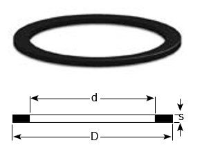
Notice! Seals are not included when you order flanges. You have to order Seals seperataly.
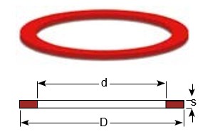
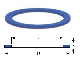
Standard sizes of PUR (VULKOLLAN® polyurethane elastomer), injection molded. Colour:blue.Other sizes of PUR (VULKOLLAN® Cast polyurethane). Colour: honey-coloured. Vulkollan® is a registered trademark of Bayer
|
Weight Appr. ≈ Kg |
Suitable for |
Dimensions ≈ mm |
Product No |
||
|
D |
d |
s |
|||
|
0,001 |
BSP 3/4” |
26 |
19 |
2 |
1498-09 |
|
0,001 |
BSP 1” |
33 |
24 |
2 |
1220-09 |
|
0,001 |
BSP 1 1/4” (DN 25 + DN 32) |
42 |
34 |
2 |
1536-09 |
|
0,002 |
BSP 1 ½ ” (DN 32 + DN 38) |
48 |
39 |
2 |
1196-09 |
|
0,003 |
BSP 1 3/4” |
54 |
44 |
2,5 |
On request |
|
0,003 |
BSP 2” |
60 |
49 |
2 |
1052-09 |
|
0,005 |
BSP 2 ½ ” |
76 |
63 |
2,5 |
1181-09 |
|
0,006 |
BSP 3” |
88 |
77 |
3 |
1110-09 |
|
0,010 |
BSP 3½” |
100 |
80 |
3 |
On request |
|
0,009 |
BSP 4” |
114 |
100 |
3 |
1295-09 |
|
0,012 |
BSP 5” ( No standard) |
140 |
124 |
3 |
On request |
|
0,016 |
BSP 6” |
164 |
150 |
3 |
1963-09 |
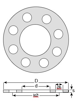
ELAPAC Flange Seals FD, QFD
|
Dimensions ≈ mm |
|
Flange Standard / Suitable for D d Øk Øh s |
|
DN 25 PN 10/16 |
108 |
78,5 |
91 |
4 x 6,5 |
2 |
- |
|
DN 32 PN 10/16 |
140 |
43 |
100 |
4 x 18 |
2 |
- |
|
DN 50 PN 6 |
140 |
61 |
110 |
4 x 15 |
2 |
- |
|
DN 50 TW 1 |
154 |
50 |
130 |
8 x 12 |
2 |
- |
|
DN 80 TW 1 |
154 |
90 |
130 |
8 x 12 |
2 |
- |
|
DN 50 PN 10/16 |
165 |
61 |
125 |
4 x 18 |
2 |
- |
|
DN 100 TW3 |
174 |
110 |
150 |
8 x 14 |
2 |
- |
|
DN 65 PN 10/16 |
185 |
76 |
145 |
4 x 18 |
2 |
- |
|
DN 80 PN 10/16 |
200 |
90 |
160 |
8 x 18 |
2 |
- |
|
DN 125 TW5 |
204 |
135 |
176 |
8 x 14 |
2 |
- |
|
DN 100 PN 10/16 |
220 |
115 |
180 |
8 x 18 |
2 |
- |
|
DN 150 TW7 |
240 |
160 |
210 |
12 x 14 |
2 |
- |
|
DN 125 PN 10/16 |
250 |
141 |
210 |
8 x 18 |
2 |
- |
|
DN 150 PN 10/16 |
280 |
169 |
240 |
8 x 22 |
2 |
- |
|
DN 200 PN 10 |
340 |
220 |
295 |
8 x 22 |
2 |
- |
|
DN 200 PN 16 |
340 |
220 |
295 |
12 x 22 |
2 |
- |
Product No - on request
First sign (letter): Indicates the type of coupling
A = API-adapter
AV = Tank Unit (EN 13081)
B = Ball Valve
C = Dust Cap
CG = Dust Cap LPG
D = Swivel
E = Tank Unit with pressure valves
F = Hose Unit (ISO 45)
G = Tank Unit (ISO 45)
GS = Tank Unit (ISO 45) with selectivity
H = Sampling Vent & Drain Unit
I = Dust Plug ISO 45
K = Dust Cap ISO 45
L = Tank Unit LPG
LC = Tank Unit Cryogenic
M = Hose Unit LPG
MC = Hose Unit Cryogenic
N = Break Away Pin
NC = Break Away Pin Cryogenic
O = Break Away Wire
P = Dust Plug
R = Pressure Cap
RG = Pressure Cap LPG
S = Hose Unit (STANAG 3756)
SN = Hose Unit int. Break Away Pin
SO = Hose Unit int. Break Away Wire
T = Tank Unit (STANAG 3756)
U = Filter / Sight Glass
V = Dust Plug LPG
WA= Hose Fittings
Second sign (numeral): Indicates the socket diameter and/or the nominal diameter
0 = 50mm or ¾”
1 = 56mm or 1”, 1 ¼”
2 = 70mm or 1 ½”, 2”
3 = 105mm or 2 ½”
4 = 119mm or 3”
5 = 164mm or 4”
V= 5”
6 = 238mm or 6”
8 = 272mm or 8”
10 = 10”
12 = 12”
Third and fourth sign (numeral): Indicates connection, (thread, flange etc.)
01 = ¾” BSP (Female)
02 = ¾” NPT (Female)
03 = 1” BSP (Female)
04 = 1” NPT (Female)
05 = 1 ¼” BSP (Female)
06 = 1 ¼” NPT (Female)
07 = 1 ½” BSP (Female)
08 = 1 ½” NPT (Female)
09 = 1 ¾” BSP (Female)
10 = 2” BSP (Female)
11 = 2” NPT (Female)
12 = 2 ½” BSP (Female)
13 = 2 ½” NPT (Female)
14 = 3” BSP (Female)
15 = 3” NPT (Female)
16 = 4” BSP (Female)
17 = 4” NPT (Female)
18 = Flange undrilled Ø156
19 = Flange undrilled Ø165
20 = Flange undrilled Ø210
21 = Flange undrilled Ø230
22 = Flange undrilled Ø254
23 = Flange DN 25 PN 10/16
24 = Flange DN 25 PN 25/40
25 = Flange DN 32 PN 10/16
26 = Flange DN 32 PN 25/40
27 = Flange DN 40 PN 10/16
28 = Flange DN 40 PN 25/40
29 = Flange DN 50 PN 25/40*
30 = Flange DN 50 PN 10/16
31 = Flange DN 50 PN 25/40
32 = Flange DN 65 PN 25/40*
33 = Flange DN 65 PN 10/16
34 = Flange DN 65 PN 25/40
35 = Flange DN 80 PN 25/40*
36 = Flange DN 80 PN 10/16
37 = Flange DN 80 PN 25/40
38 = Flange DN 100 PN 25/40*
39 = Flange DN 100 PN 10/16
40 = Flange DN 100 PN 25/40
41 = Flange DN 125 PN 6
42 = Flange DN 125 PN 10/16
43 = Flange DN 125 PN 25/40
44 = Flange DN 150 PN 6
45 = Flange DN 150 PN 10/16
46 = Flange DN 150 PN 25/40
47 = Flange DN 20 PN 10/16
48 = Flange DN 20 PN 25/40
49 = Flange ¾” ANSI Class 150
50 = Flange ¾” ANSI Class 300
51 = Flange 1” ANSI Class 150
52 = Flange 1” ANSI Class 300
53 = Flange 1 ¼” ANSI Class 150
54 = Flange 1 ¼” ANSI Class 300
55 = Flange 1 ½” ANSI Class 150
56 = Flange 1 ½” ANSI Class 300
57 = Flange 2” ANSI Class 150
58 = Flange 2” ANSI Class 300
59 = Flange 2 ½” ANSI Class 150
60 = Flange 2 ½” ANSI Class 300
61 = Flange 3” ANSI Class 150
62 = Flange 3” ANSI Class 300
63 = Flange 4” ANSI Class 150
64 = Flange 4” ANSI Class 300
65 = Flange TW 1 (3” - DN 80)
66 = Flange TW 3 (4” - DN 100)
67 = Flange 3” T.T.M.A.
68 = Flange 4” T.T.M.A.
69 = ¾” BSP (Male)
70 = ¾” NPT (Male)
71 = 1” BSP (Male)
72 = 1” NPT (Male)
73 = 1 ¼” BSP (Male)
74 = 1 ¼” NPT (Male)
75 = 1 ½” BSP (Male)
76 = 1 ½” NPT (Male)
77 = 1 ¾” BSP (Male)
78 = 2” BSP (Male)
79 = 2” NPT (Male)
80 = 2 ½” BSP (Male)
81 = 2 ½” NPT (Male)
82 = 3” BSP (Male)
83 = 3” NPT (Male)
84 = 4” BSP (Male)
85 = 4” NPT (Male)
86 = Weld.flange 2” Ø60,5 inner
87 = Flange TW 1 (2” DN50)
88 = Weld.flange 2” Ø50-Ø70 (flat)
89 = Weld.flange 2” Ø57 (int. chamfer)
90 = Weld.flange 2” Ø60 (outer chamfer)
91 = Weld.flange 3” Ø75-Ø90 (flat)
92 = Weld.flange 3” Ø76 (int. chamfer)
93 = Weld.flange 3” Ø89 (outer. chamfer)
94 = Weld.flange 4” Ø100-Ø120 (flat)
95 = Weld.flange 4” Ø102 (int. chamfer)
96 = Weld.flange 4” Ø108 (int. chamfer)
97 = Weld.flange 4” Ø114 (outer. chamfer)
98 = Flange TW 1 (2” - DN 50)
with drain connection
99 = Flange DN 150 PN 25
100 = Flange 6” ANSI Class 150
101 = Flange 6” ANSI Class 300
102 = Flange DN 200 PN 10
103 = Flange DN 200 PN 16
104 = Flange DN 200 PN 25
105 = Flange 8” ANSI Class 150
106 = Flange 8” ANSI Class 300
107 = Flange Square ISO 45
108 = S60x6 (Female)
109 = S60x6 (Male)
110 = 6” BSP (Female)
111 = 6” NPT (Female)
112 = W2” - 7 (Female)
113 = Weld.flange 3” Ø92 inner
114 = Square flange, 4 holes
115 = 6” BSP (Male)
116 = 6” NPT (Male)
117 = 8” NPT (Female)
118 = 4” Victaulic
119 = Flange DN 50 PN 25/40**
120 = Flange DN 65 PN 25/40**
121 = Flange DN 80 PN 25/40**
122 = Flange DN 100 PN 25/40**
123 = W2” - 7 (Male)
124 = 5” NPT (Female)
125 = 5” NPT (Male)
126 = Flange DN 100 PN6
127 = Flange DN 80 PN6
128 = Flange DN 65 PN6
129 = Flange DN 50 PN6
130 = Flange 8” ANSI Class 600
131 = W90x1/6” (Female)
132 = ½” NPT (Female)
133 = ½” BSP (Female)
134 = Flange ø184.2, 6 holes
135 = Flange TW 7 (6” - DN 150)
136 = 4” ASSPT (Female)
137 = Triclamp DN 25
138 = M54x 1,5 (Female)
139 = Triclamp DN 50
140 = Weld.flange Ø73 (outer chamfer)
141 = 3” Victaulic
142 = Flange 5” ANSI Class 150
143 = 3” Ball valve
144 = 2” Victaulic
145 = 3” BSPT (Male)
146 = 5” Victaulic
147 = 2” BSPT (Female)
148 = 2” BSPT (Male)
149 = 1 ½” Victaulic
150 = 2 ½” Victaulic
151 = Flange 1” DIN 11864-2
152 = Flange 2” DIN 11864-2
153 = Flange ø135, 8xM6
154 = 4” BSPT (Female)
155 = 4” BSPT (Male)
156 = Weld flange 2” ø61,5 (inner)
157 = 3” BSPT (Female)
158 = Weld end 1½” ø48 (outer)
159 = Thread TR 57x4
160 = Flange 2” BS10 Table D
161 = Flange 12” ANSI Class 150
162 = Flange 10” ANSI Class 150
163 = Flange DN 250 PN 16
164 = M130x6 (Female)
165 = Flange 10” ANSI Class 300
166 = ACME 1¼” (Female)
167 = ACME 1¾” (Female)
168 = ACME 2¼” (Female)
169 = ACME 3¼” (Female)
170 = ACME 1¼” (Male)
171 = ACME 1¾” (Male)
172 = ACME 2¼” (Male)
173 = ACME 3¼” (Male)
174 = Weld.flange Ø76 (outer. chamfer)
175 = Flange DN 15 PN 10/16
176 = Flange DN 15 PN 25/40
177 = M130x6 (Male)
178 = Flange 6” T.T.M.A.
179 = Flange DN 80 PN 25/40***
180 = ½” NPT (Male)
181 = ½” BSP (Male)
182 = 5” BSP (Female)
183 = 5” BSP (Male)
184 = Weld end 8” ø219 (outer)
185 = Weld end 6” ø168 (outer)
186 = Flange DN 250 PN 25
187 = Flange 2” T.T.M.A.
188 = Flange 3” BS10 Table D
189 = Flange ½” ANSI Class 150
190 = Flange 1” ANSI Class 150 Flat Face
191 = Flange 12” ANSI Class 300
192 = Flange DN250 PN10
193 = Weld end Ø114 Schedule 40
194 = Weld end Ø114 Schedule 80
195 = 6” Victaulic
196 = 1” Victaulic
197 = DN 125 JIS 5K
198 = DN 100 JIS 5K
199 = DN 80 JIS 5K
200 = DN 50 JIS 5K
201 = DN 40 JIS 5K
202 = Flange 2” DIN 11864-3
203 = 3½” BSP (Female)
204 = Flange Ø110, Ø86/Ø5.5 (6x)
205 = Weld end Ø60 Schedule 80
206 = Weld end Ø89 Schedule 40
207 = Weld end Ø89 Schedule 80
208 = Flange DN 25 PN 6
209 = Flange DN 32 PN 6
210 = Flange DN 40 PN 6
211 = DN 125 JIS 10K
212 = DN 100 JIS 10K
213 = DN 80 JIS 10K
214 = DN 50 JIS 10K
215 = DN 40 JIS 10K
216 = Flange DN 80, holes Ø14 (6x)
217 = Flange 5” ANSI Class 300
* EN 1092-1:2001 Type E: Spigot ** EN 1092-1:2001 Type F *** EN 1092-1:2001 Type C
Fifth sign (letter): Indicates version
A = Version No.1 (Machined from bar)
B = Version No.2 (Casted)
C = Version No.3 (Kokill casted)
D = Sep. piston guide
E = Injection moulded
F = 6” Flange Hydrant
G = Drain connection
H = Leaf spring lock
I = Bended Tank Unit Short (15°)
J = Bended Tank Unit (15°)
K = Short Tank Unit/Swivel
N = Non Return Valve
P = Pressure (Custom)
S = Sight Glass
T = Transparent
U = Stop before disconnected
Sixth sign (numeral): Indicates material in the coupling body
1 = Aluminium
2 = Brass
3 = Steel
4 = Stainless steel A4 (316)
5 = Stainless steel A2 (304)
6 = Titan
7 = Hastelloy
8 = PVDF
9 = PEEK
K = Inconel
Seventn sign (numeral): Indicates material in the innerparts or other components
1 = Aluminium
2 = Brass
3 = Steel
4 = Stainless steel A4 (316)
5 = Stainless steel A2 (304)
6 = Titan
7 = Hastelloy
8 = PVDF
9 = PEEK
K = Inconel
Eight and Ninth sign (numeral): Indicates the O-ring material in the coupling
01 = Viton® (FPM/FKM)
02 = Nitrile (NBR)
03 = EPDM
04 = Kalrez® (FFKM) 6375
05 = NBR Low temp
06 = Teflon® (PTFE)
07 = Neoprene® (CR)
08 = Silicone (Q)
09 = Vulkollan® (PUR)
10 = Butyl (IIR)
11 = Nitrile (Gasol NBR 70 K-6)
12 = Perfluorelastomer (FFPM/FFKM)
13 = PVC / NBR
14 = Fluorsilicone rubber (MFQ)
15 = FEP encapsulated silicone
16 = Hypalon® (CSM)
17 = Chemraz® 505 (FFKM)
18 = Xyflour® 860 (AFKM)
19 = Zetpol® / Therban® (HNBR)
20 = NBR 90 shore
21 = Viton®-GF (Special Viton quality)
22 = Composite
23 = Viton® GFLT-S
24 = Viton® GLT
25 = Klingerit®
26 = POM
27 = Epiclorhydrin (ECO)
28 = Viton® GFLT-S NMO
31 = Viton® 90 Shore (FPM/FKM)
33 = EPDM 291
34 = Kalrez® 0040
37 = Chemraz® 510 (90 Shore)
40 = FEP PTFE encapsulated Viton®
50 = Kalrez® (PFPM) 1050LF
51 = Nylon® (PA)
61 = Viton® (FPM), FDA, USP C6 & ADI
62 = Nitrile (NBR), FDA, USP C6 & ADI
63 = EPDM, FDA, USP C6 & ADI
64 = Kalrez® (FFKM) 6230, FDA, USP C6 & ADI
66 = PTFE (Virgin), FDA
71 = FPM/FKM Low Temp
77 = Chemraz® SD517, FDA, USP C6 & ADI
83 = EPDM BA
Tenth sign (letter): Used for extra
A = Flat seal, Teflon®(PTFE)
B = Flat seal, Vulkollan®(PUR)
C = 2-way Ball Valve
D = Flat seal, Viton® (FPM)
DA = Double Acting (Ball Valve)
E = None projecting piston spindle
F = Flange thickness acc. to standard
G = Hypalon
H = Nitrile (NBR)
I = Emco comp
J = EPDM
K = Locked piston guide
L = Locked thread
M = Modified Cam Curve
N = No Branding
NA = No Actuator (Ball Valve)
P = Pressure Equalizing Valve
Q = Reduced bore diameter
(Argus,Hydrant)
R = Hose unit with int. Break Away
S = Single Argus valve (Hydrant)
SR = Spring Return (Ball Valve)
T = TW-Flange extended circles
U = Pressure Bleeding Valve 16 bar
U5 = Pressure Bleeding valve 5 bar
U20 = Pressure Bleeding valve 20 bar
V = Locking house unit
W = Double ball race
X = Special surface treatment
Z = Excentric tank unit
-RA = Racing
-LC = Locking Cap
-S = FEP O-ring in Hose Unit swivel
-ST = Steam
-XL = Oversized swivel
-45 = 45 Mesh
-60 = 60 Mesh
-10 = 100 Mesh
Didn't find the right Dry Aviation Couplings?
Fill in the form below, and we'll assist you further!
Curious about our blog? Check out all our items here!
Contact us here


 Nederlands
  Deutsch