Personal and expert advice
25 years of experience
Fast delivery times
Competitive prices
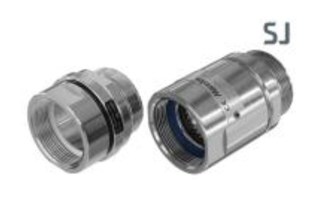
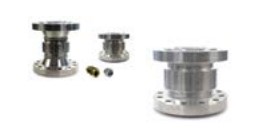
Swivel Joints
Swivel Joints are used in the industry wherever a movable pipe-connection system between two equipment parts is needed. Avoiding one of the biggest causes of premature hose failure. Torque stress is the largest single cause of PTFE and Stainless steel convoluted hose failure.
The swivel joints are designed for slow rotary motions under the influence of high internal pressures and/or external stress such as traction and bending forces.
With an appropriate combination of swivel joints nearly all movements from the simple rotation or swivelling motion up to motional actions in space can be realized.
The use of hose swivels avoids torsion of hose assemblies, i.e. in filling machines, and improves the handling and coupling of nozzles for refuelling of petroleum based products and chemicals.

NOTE
Unsuitable for high bending moments. Heavy Duty Swivels should be used in these applications.
Low maintenance
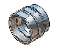
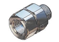
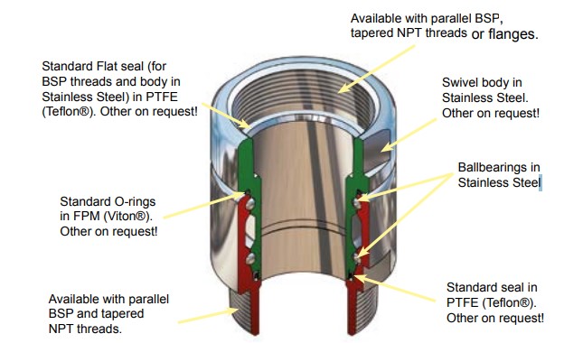
Each unit consist of two body halves. Stainless Steel balls and a single spring assisted O-ring seal.
Compact external dimensions
High flow rate / low pressure drop
Full range of sizes, materials, seals and connections
Minimal maintenance requirements
Safety
Swivel function - allows the hose to relax to it´s natural rest position whilst allowing freedom of movement without imparting torque stress at the point of connection - Torque stress is the largest single cause of Composite, PTFE and Stainless Steel convoluted hose failure.
Economical
Cost effective solution to prolong lifetime of hoselines.

Combinations of sizes, connections and materials
| Swivel maten |
|
3/4” |
1” |
1 1/4” |
1 1/2” |
2” |
2 1/2” |
3” |
4” |
|
Threads (Female / Male1)) |
|
BSP (ISO 228) |
|
NPT (ASME/ANSI 1.20.1 |
|
BSPT (EN 10226) |
|
ACME |
|
Weld end |
|
Flanges |
|
DIN Flange (ISO 1092 PN 10/16, PN 25/40 (Type A, B, E, F 2) ) |
|
ASA Flange (ASME/ANSI 16.5) |
|
TW-Flange (DIN 28459) |
|
T.T.M.A |
1) Any combinations of male and female threads is possible.
2) Se page14 for illustrations of different types of DIN-flanges.
| Standard materials and standard seals |
| Component | Material | Material standard | Operation temp | O-ring | Flat seal |
| Body |
Aluminium
Brass
Stainless Steel |
EN 755 - AW-6262-T6 EN 1706-AC-42100-T6 EN 12164 - CW614N EN 1982 - CB491K-GS EN 10272 - 1.4404+AT EN 10213 - 1.4409+AT |
-40oC to 250oC |
FPM/KFM (Viton®) |
PUR (Vulkollan®)
PUR (Vulkollan®)
PTFE (Teflon®) |
Working Pressure: (10 bar) - 300 psi (20 bar)
We manufacture Swivels in different sizes, connections and materials on request!
| One side | Other side |
| BSP/NPT Female | BSP/NPT Female |
| One side | Other side |
| BSP/NPT Female | BSP/NPT Male |
| One side | Other side |
| BSP/NPT Male | BSP/NPT Male |
| One side | Other side |
| BSP/NPT Thread | Flange |
| One side | Other side |
| Flange | Flange |
| One side | Other side |
| Weld end | Weld end *) |
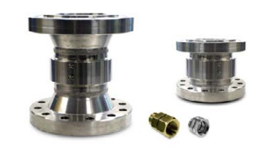
The swivel Heavy duty is designed especially for hose rails to load and unload products like Aliphatic and Aromatic hydrocarbons, Alcohols and Amines, Ether and Ester, Glycos and Water, Liquid Fertilizers, Acids and Lyes.
NOTE
Please ask us for your special application.
• Offshore hose reels ship-to-shore
• Oil platform loading rigs
• Marine and industrial loading arms
• Hoses for road and rail tanker
• Chemical and petrochemical liquids
and liquefied gases.
Low maintenance
Each unit consist of two body halves. Stainless Steel balls and a single spring assisted O-ring seal.
Compact external dimensions
High flow rate / low pressure drop
Full range of sizes, materials, seals and connections
Minimal maintenance requirements
Safety
Swivel function - allows the hose to relax to it´s natural rest position whilst allowing freedom ofmovement without imparting torque stress at thepoint of connection - Torque stress is the largestsingle cause of Composite, PTFE and Stainless Steel convoluted hose failure.
Economical
Cost effective solution to prolong lifetime of hoselines.
Combinations of sizes, connections and materials
| Swivel sizes |
|
2" |
3" |
4" |
5" |
6” |
8" |
10" |
|
Threads (Female / Male1)) |
|
BSP (ISO 228) |
|
NPT (ASME/ANSI 1.20.1 |
|
BSPT (EN 10226) |
|
ACME |
|
Victaulic |
|
Weld end |
|
Flanges |
|
DIN Flange (ISO 1092 PN 10/16, PN 25/40 (Type A, B, E, F 2) ) |
|
ASA Flange 150 psi / 300 psi (ASME/ANSI 16.5) |
|
TW-Flange (DIN 28459) |
|
T.T.M.A |
1) Any combinations of male and female threads is possible.
2) Se page 14 for illustrations of different types of DIN-flanges
| Standard materials and standard seals |
| Component | Material | Material standard | Operation temp | Seal | Flat seal |
| Body |
Aluminium
Stainless Steel |
EN 755 - AW-6262-T6 EN 1706-AC-42100-T6 EN 10272 - 1.4404+AT EN 10213 - 1.4409+AT |
-100oC to 250oC |
PTFE (Teflon®) |
PUR (Vulkollan®)
PTFE (Teflon®) |
Working Pressure: 150 psi (10 bar)-1800 psi (125 bar)
We manufacture Swivels in different sizes, connections and materials on request!
| one side | Other side |
| BSP/NPT F | BSP/NPT F |
| One side | Other side |
| BSP/NPT F | BSP/NPT M |
| One side | Other side |
| BSP/NPT M | BSP/NPT M |
| One side | Other side |
| Thread | Flange |
| One side | Other side |
| Flange | Flange |
| One side | Other side |
| Victaulic | Victaulic*) |
| One side | Other side |
| Weld end | Weld end *) |
| Compact version |
NOTE
For loading arm applications, contact our technical department
Connections (thread, flange etc.)

O-ring / Seals materials
Used for extra (last letter)
A = Flat Seal, PTFE (Teflon®)
B = Flat Seal PUR (Vulkollan®)
D = Flat Seal FPM (Viton®)
W = Double Ball Race
E.G. Code No: D10794401A=Hose Swivel, Single ball bearing
One side: 2" BSP (Female) Other side: 2" NPT (Male)
Material: Stainless Steel, Flat Seal PTFE (Teflon®)
E.G. Code No: D85614401W=Swivel, Double ball race
One side: 4" NPT (Male) Other side: Flange 3", ANSI (ASA) 150 psi
Material: Stainless Steel
Type A Flat face Type B Raised face Type C Tongue Type D Groove
Type E Spigot Type F Recess Type G O-ring Spigot Type G O-ring Groove
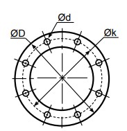
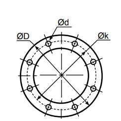
Ø D = Diameter
Ø k = Centre diameter
n = Numer of holes
Ø d = Hole diameter
|
EN 1092-1 |
|
DN |
PN 10 |
PN 16 |
PN 25 |
PN 40 |
||||||||||||
|
ØD |
Øk |
n |
Ød |
ØD |
Øk |
n |
Ød |
ØD |
Øk |
n |
Ød |
ØD |
Øk |
n |
Ød |
|
|
20 |
mm 105 |
75 |
4 |
14 |
105 |
75 |
4 |
14 |
105 |
75 |
4 |
14 |
105 |
75 |
4 |
14 |
|
|
inch 4.13 |
2.95 |
0.55 |
4.13 |
2.95 |
0.55 |
4.13 |
2.95 |
0.55 |
4.13 |
2.95 |
0.55 |
||||||
|
25 |
mm |
115 |
85 |
4 |
14 |
115 |
85 |
4 |
14 |
115 |
85 |
4 |
14 |
115 |
85 |
4 |
14 |
|
inch |
4.53 |
3.35 |
0.55 |
4.53 |
3.35 |
0.55 |
4.53 |
3.35 |
0.55 |
4.53 |
3.35 |
0.55 |
|||||
|
32 |
mm |
140 |
100 |
4 |
18 |
140 |
100 |
4 |
18 |
140 |
100 |
4 |
18 |
140 |
100 |
4 |
18 |
|
inch |
5.51 |
3.94 |
0.71 |
5.51 |
3.94 |
0.71 |
5.51 |
3.94 |
0.71 |
5.51 |
3.94 |
0.71 |
|||||
|
40 |
mm |
150 |
110 |
4 |
18 |
150 |
110 |
4 |
18 |
150 |
110 |
4 |
18 |
150 |
110 |
4 |
18 |
|
inch |
5.91 |
4.33 |
0.71 |
5.91 |
4.33 |
0.71 |
5.91 |
4.33 |
0.71 |
5.91 |
4.33 |
0.71 |
|||||
|
50 |
mm |
165 |
125 |
4 |
18 |
165 |
125 |
4 |
18 |
165 |
125 |
4 |
18 |
165 |
125 |
4 |
18 |
|
inch |
6.50 |
4.92 |
0.71 |
6.50 |
4.92 |
0.71 |
6.50 |
4.92 |
0.71 |
6.50 |
4.92 |
0.71 |
|||||
|
65 |
mm |
185 |
145 |
4 |
18 |
185 |
145 |
4 |
18 |
185 |
145 |
8 |
18 |
185 |
145 |
8 |
18 |
|
inch |
7.28 |
5.71 |
0.71 |
7.28 |
5.71 |
0.71 |
7.28 |
5.71 |
0.71 |
7.28 |
5.71 |
0.71 |
|||||
|
80 |
mm |
200 |
160 |
8 |
18 |
200 |
160 |
8 |
18 |
200 |
160 |
8 |
18 |
200 |
160 |
8 |
18 |
|
inch |
7.87 |
6.30 |
0.71 |
7.87 |
6.30 |
0.71 |
7.87 |
6.30 |
0.71 |
7.87 |
6.30 |
0.71 |
|||||
|
100 |
mm |
220 |
180 |
8 |
18 |
220 |
180 |
8 |
18 |
235 |
190 |
8 |
22 |
235 |
190 |
8 |
22 |
|
inch |
8.66 |
7.09 |
0.71 |
8.66 |
7.09 |
0.71 |
9.25 |
7.48 |
0.87 |
9.25 |
7.48 |
0.87 |
|||||
|
125 |
mm |
250 |
210 |
8 |
18 |
250 |
210 |
8 |
18 |
270 |
220 |
8 |
26 |
270 |
220 |
8 |
26 |
|
inch |
9.84 |
8.27 |
0.71 |
9.84 |
8.27 |
0.71 |
10.63 |
8.66 |
1.02 |
10.63 |
8.66 |
1.02 |
|||||
|
150 |
mm |
285 |
240 |
8 |
22 |
285 |
240 |
8 |
22 |
300 |
250 |
8 |
26 |
300 |
250 |
8 |
26 |
|
inch |
11.22 |
9.45 |
0.87 |
11.22 |
9.45 |
0.87 |
11.81 |
9.84 |
1.02 |
11.81 |
9.84 |
1.02 |
|||||
|
200 |
mm |
340 |
295 |
8 |
22 |
340 |
295 |
12 |
22 |
360 |
310 |
12 |
26 |
375 |
320 |
12 |
30 |
|
inch |
13.39 |
11.61 |
0.87 |
13.39 |
11.61 |
0.87 |
14.17 |
12.20 |
1.02 |
14.76 |
12.60 |
1.18 |
|||||
|
250 |
mm |
395 |
355 |
12 |
22 |
405 |
355 |
12 |
26 |
425 |
370 |
12 |
30 |
450 |
385 |
12 |
33 |
|
inch |
15.55 |
13.98 |
0.87 |
15.94 |
13.98 |
1.02 |
16.73 |
14.57 |
1.18 |
17.72 |
15.16 |
1.30 |
|||||
|
300 |
mm |
445 |
400 |
12 |
22 |
460 |
410 |
12 |
26 |
485 |
430 |
16 |
30 |
515 |
450 |
16 |
33 |
|
inch |
17.52 |
15.75 |
0.87 |
18.11 |
16.14 |
1.02 |
19.09 |
16.93 |
1.18 |
20.28 |
17.65 |
1.30 |
|||||
|
EN 1092-1 EN 1092-1 PN 6 |
DIN. |
|
DIN 2631 |
|
|
EN 1092-1 PN 10 |
DIN 2632 |
|
EN 1092-1 PN 16 |
DIN 2633 |
|
EN 1092-1 PN 25 |
DIN 2634 |
|
EN 1092-1 PN 40 |
DIN 2635 |
|
EN 1092-1 Type B Raised Face |
DIN 2526 Form C |
|
EN 1092-1 Type C Tongue |
DIN 2512 Form F |
|
EN 1092-1 Type D Groove |
DIN 2512 Form N |
|
EN 1092-1 Type E Spigot |
DIN 2513 Form V |
|
EN 1092-1 Type F Recess |
DIN 2513 Form R |
Ø D = Diameter
Ø k = Centre diameter
n = Numer of holes
Ø d = Hole diameter
|
ANSI (ASA) B 16,5 |
|
INCH |
150 psi |
300 psi |
||||||
|
ØD |
Øk |
n |
Ød |
ØD |
Øk |
n |
Ød |
|
|
3/4” |
mm |
98,4 |
69,8 |
4 |
15,9 |
117,5 |
82,5 |
4 |
19 |
|
inch |
3 7/8 |
2 3/4 |
5/8 |
4 5/8 |
3 1/4 |
3/4 |
|||
|
1” |
mm |
107,7 |
79,4 |
4 |
15,9 |
123,8 |
88,9 |
4 |
19 |
|
inch |
4 1/4 |
3 1/8 |
5/8 |
4 7/8 |
3½ |
3/4 |
|||
|
1 1/4” |
mm |
117,5 |
88,9 |
4 |
15,9 |
133,3 |
98,4 |
4 |
19 |
|
inch |
4 5/8 |
3½ |
5/8 |
5 1/4 |
3 7/8 |
3/4 |
|||
|
1 1/2” |
mm |
127 |
98,4 |
4 |
15,9 |
155,6 |
114,3 |
4 |
22,2 |
|
inch |
5 |
3 7/8 |
5/8 |
6 1/8 |
4½ |
7/8 |
|||
|
2” |
mm |
152,4 |
120,6 |
4 |
19 |
165,1 |
127 |
8 |
19 |
|
inch |
6 |
4 3/4 |
3/4 |
6½ |
5 |
3/4 |
|||
|
2 1/2” |
mm |
177,8 |
139,7 |
4 |
19 |
190,5 |
149,2 |
8 |
22,2 |
|
inch |
7 |
5½ |
3/4 |
7½ |
5 7/8 |
7/8 |
|||
|
3” |
mm |
190,5 |
152,4 |
4 |
19 |
209,5 |
168,3 |
8 |
22,2 |
|
inch |
7½ |
6 |
3/4 |
8 1/4 |
6 5/8 |
7/8 |
|||
|
4” |
mm |
228,5 |
190,5 |
8 |
19 |
254 |
200 |
8 |
22,2 |
|
inch |
9 |
7½ |
3/4 |
10 |
7 7/8 |
7/8 |
|||
|
5” |
mm |
254 |
215,9 |
8 |
22,2 |
279,4 |
234,9 |
8 |
22,2 |
|
inch |
10 |
8½ |
7/8 |
11 |
9 1/4 |
7/8 |
|||
|
6” |
mm |
279,4 |
241,3 |
8 |
22,2 |
317,5 |
269,9 |
12 |
22,2 |
|
inch |
11 |
9½ |
7/8 |
12½ |
10 5/8 |
7/8 |
|||
|
8” |
mm |
342,9 |
298,4 |
8 |
22,2 |
381 |
330,2 |
12 |
25,4 |
|
inch |
13½ |
11 3/4 |
7/8 |
15 |
13 |
1 |
|||
|
10” |
mm |
406,4 |
361,9 |
12 |
25,4 |
444,5 |
387,3 |
16 |
28,6 |
|
inch |
16 |
141/4 |
1 |
17½ |
15 1/4 |
1 1/8 |
|||
|
12” |
mm |
482,6 |
431,8 |
12 |
25,4 |
520,7 |
450,8 |
16 |
31,7 |
|
inch |
19 |
17 |
1 |
20½ |
17 3/4 |
1 1/4 |
|
TW DIN 28459 |
|
|
DN |
ØD |
Øk |
n |
Ød |
|
TW1 |
50 |
mm |
154 |
130 |
8 |
11 |
|
inch |
6.06 |
5.12 |
|
0.43 |
||
|
TW1 |
80 |
mm |
154 |
130 |
8 |
11 |
|
inch |
6.06 |
5.12 |
|
0.43 |
||
|
TW3 |
100 |
mm |
174 |
150 |
8 |
14 |
|
inch |
6.85 |
5.91 |
|
0.55 |
||
|
TW5 |
125 |
mm |
204 |
176 |
8 |
14 |
|
inch |
8.03 |
6.93 |
|
0.55 |
||
|
TW7 |
150 |
mm |
240 |
210 |
12 |
14 |
|
inch |
9.45 |
8.27 |
|
0.55 |
|
T.T.M.A |
|
INCH |
ØD |
Øk |
n |
Ød |
|
2” |
mm |
114,3 |
95,3 |
6 |
11,1 |
|
inch |
4.50 |
3.75 |
0.44 |
||
|
3” |
mm |
142,9 |
123,8 |
8 |
11,1 |
|
inch |
5.63 |
4.87 |
0.44 |
||
|
4” |
mm |
168,3 |
149,2 |
8 |
11,1 |
|
inch |
6.63 |
5.87 |
0.44 |
||
|
5” |
mm |
196,9 |
177,8 |
12 |
11,1 |
|
inch |
7.75 |
7.00 |
0.44 |
||
|
6” |
mm |
228,6 |
206,4 |
12 |
11,1 |
|
inch |
9.00 |
8.13 |
0.44 |
||
|
8” |
mm |
276,2 |
257,2 |
16 |
11,1 |
|
inch |
10.87 |
10.13 |
0.44 |
Mounting instruction
When installing Mann Tek equipment to new pipe work, tanks, etc. ensure the system is free from debris that may be transferred through the coupling. Where the hose or loading arm assembly is the primary static dissipation or earth route, the electrical continuity value of the assembly shall be checked to ensure regulatory compliance. Special attention should be paid to the balancing of loading arms. The weight of the coupling plus transfer media should be taken into account at the specification stage. It is usual for loading arm balance settings to account of weight variations due to differences in the full / empty cycle.
The loading arm should be set to balance in the condition present at the time of connection. For example, should the loading arm be empty at the time of connection then it should be balanced in the empty condition.
The Mann-Tek product can be installed directly in the product line and is ready for use after
removing the transport protection. The installation is recommended as follows:
a. Remove the packaging and the flange protection
b. Check the coupling for damages before mounting.
c. To prevent damages during mounting a suitable wrench should be used for the intended bolts and nuts.
d. Ensure that the product line is empty and all valves are close
before you connect the coupling into the line.
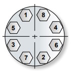
e. Set in all bolts first and tighten them by hand. Then increase the tightening torque in 2 steps up to the
recommended value in the following table. Proceed every time according to the sequence shown in g.
f. Tightening torque1) for bolts:
|
Metric |
|
|
Size |
8.8 |
|
M8 |
24 Nm |
|
M10 |
50 Nm |
|
M12 |
85 Nm |
|
M16 |
210 Nm |
|
M20 |
410 Nm |
|
M22 |
550 Nm |
|
M24 |
700 Nm |
|
Inch Size A193 B7 |
|
|
5/16 -18 UNC |
16 lbf-ft |
|
3/8 -16 UNC |
29 lbf-ft |
|
1/2 -13 UNC |
70 lbf-ft |
|
5/8 -11 UNC |
139 lbf-ft |
|
3/4 -10 UNC |
243 lbf-ft |
|
7/8 -9 UNC |
389 lbf-ft |
|
1 -8 UNC |
582 lbf-ft |
4 Bolt Pattern 8 Bolt Pattern 12 Bolt Pattern


The start-up may take place only when the Mann-Tek product has been mounted as instructed and the necessary function tests and leak tests have been conducted by the approved authorities.
1) The torque forces recommended bases on a thread friction coefficient μ=0,14 and a standard flat seal
according to EN 1514-1
Sealing NPT threads can be an exasperating experience if certain techniques are not followed. The following tips will help alleviate many common problems in thread sealing:
1. Always use some type of sealant (tape or paste) and apply sealant to male thread only. If using a hydraulic sealant, allow sufficient curing time before system is pressurized.
2. When using tape sealant, wrap the threads in a clockwise motion starting at the first thread and, as layers are applied, work towards the imperfect (vanishing) thread. If the system that the connection being made to cannot tolerate foreign matter (i.e. air systems), leave the first thread exposed and apply the tape sealant as outlined above.
3. When using paste sealant, apply to threads with a brush, using the brush to work the sealant into the threads. Apply enough sealant to fill in all the threads all the way around.
4. When connecting one stainless steel part to another stainless steel part that will require future disassembly, use a thread sealant that is designed for stainless steel. This stainless steel thread sealant is also useful when connecting aluminium to aluminium that needs to be disconnected in the future. These two materials gall easily, and if the correct sealant is not used, it can be next to impossible to disassemble.
5. When connecting parts made of dissimilar metals (i.e. steel and aluminium), standard tape or paste sealant per forms satisfactor.
6. For sizes 2” and below, tape or paste performs satisfactory. When using thread tape, four wraps (covering all necessary threads) is usually sufficient.
7. For sizes 2½” and above, thread paste is recommended. If thread tape is used, eight wraps (covering all necessary threads) is usually sufficient. Apply more wraps if necessary.
8. For stubborn to seal threads, apply a normal coating of thread paste followed by a normal layer of thread tape.
9. For extremely stubborn to seal threads, apply a normal coating of thread paste followed by a single layer of gauze bandage followed by a normal layer of thread tape.
10. Over-tightening threads can be just as detrimental as insufficient tightening. For sizes 2” and below, hand tighten the components and, with a wrench, tighten 3 full turns. For sizes 2½” and above, hand tighten the components and, with a wrench, tighten 2 full turns.
Caution!
When this procedure is done, the connection becomes permanent. Extreme measures will be necessary to disconnect these components. All other measures to seal the threads should be explored prior to use of this technique.
The threads are parallel with flat sealing surface.
This allows to use the full thread length for screwed-on parts. The largest possible transfer of force is guaranteed for short length. The thread seal behind the relief groove of the thread cannot drop out.
Simple screwing down, makes a safe connection. Subsequent tightening during operation is possible at any time. Change of seal and new assembly do not require any expert knowledge.
The European standardisations for hose assemblies require parallel threads with flat seals, because of the advantages.
|
weight ≈kg |
Thread BSP |
Materials Application |
Dimensions ≈ mm |
Product No |
||
|
D |
d |
s |
||||
|
0,001 |
BSP ½” |
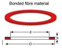
PTFE ( Teflon®) white , massive continuously hard, universally resistant
Teflon® is a registered trademark of DuPont |
20 |
13 |
2 |
On request |
|
0,001 |
BSP 3/4” |
26 |
19 |
2 |
1498-06 |
|
|
0,002 |
BSP 1” |
33 |
24 |
2 |
1220-06 |
|
|
0,003 |
BSP 1 1/4” |
42 |
34 |
2 |
1536-06 |
|
|
0,003 |
BSP 1 ½” |
48 |
39 |
2 |
1196-06 |
|
|
0,004 |
BSP 2” |
60 |
49 |
2 |
1052-06 |
|
|
0,007 |
BSP 2 ½” |
76 |
63 |
2,5 |
1181-06 |
|
|
0,006 |
BSP 3” |
88 |
77 |
3 |
1110-06 |
|
|
0,009 |
BSP 4” |
114 |
100 |
3 |
1295-06 |
|
|
0,016 |
BSP 6” |
164 |
150 |
3 |
1963-06 |
|
|
0,001 |
BSP ½” |
Thermopac asbestos free, light hard. Especially for hot oils and hot bitumen up to 250º C and for hot water and saturated steam up to 25 bar. |
20 |
13 |
2 |
On request |
|
0,001 |
BSP 3/4” |
26 |
19 |
2 |
1498-25 |
|
|
0,002 |
BSP 1” |
33 |
24 |
2 |
1220-25 |
|
|
0,002 |
BSP 1 1/4” |
42 |
34 |
2 |
1536-25 |
|
|
0,003 |
BSP 1 ½” |
48 |
39 |
2 |
1196-25 |
|
|
0,004 |
BSP 2” |
60 |
49 |
2 |
1052-25 |
|
|
0,005 |
BSP 2 ½” |
76 |
63 |
3 |
1181-25 |
|
|
0,009 |
BSP 3” |
88 |
77 |
3 |
1110-25 |
|
|
0,013 |
BSP 4” |
114 |
100 |
3 |
1295-25 |
|
|
0,016 |
BSP 6” |
164 |
150 |
3 |
1963-25 |
|
|
0,001 |
BSP 1/2” |
FPM/FKM (Viton®) soft for aromatic hydrocarbons and hot oils.
Viton® is a registered trademark of DuPont |
20 |
13 |
2 |
On request |
|
0,001 |
BSP 3/4” |
26 |
19 |
2 |
1498-01 |
|
|
0,002 |
BSP 1” |
33 |
24 |
2 |
1220-01 |
|
|
0,002 |
BSP 1 1/4” |
42 |
34 |
2 |
1536-01 |
|
|
0,003 |
BSP 1 ½” |
48 |
39 |
2 |
1196-01 |
|
|
0,004 |
BSP 2” |
60 |
49 |
2 |
1052-01 |
|
|
0,006 |
BSP 2 ½” |
76 |
63 |
3 |
1181-01 |
|
|
0,008 |
BSP 3” |
88 |
77 |
3 |
1110-01 |
|
|
0,014 |
BSP 4” |
114 |
100 |
3 |
1295-01 |
|
|
0,016 |
BSP 6” |
164 |
150 |
3 |
1963-01 |
|
|
0,001 |
BSP 3/4” |
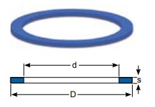
PUR (Vulkollan®) Flat seals type of polyurethane, hightly resitant to abrasion, non-toxic. Shore hardness=900 . For all petroleum based products and many solvents. Colour:Blue
Vulkollan® is a registe- red trademark of Bayer |
26 |
19 |
2 |
1498-09 |
|
0,001 |
BSP 1” |
33 |
24 |
2 |
1220-09 |
|
|
0,001 |
BSP 1 1/4” |
42 |
34 |
2 |
1536-09 |
|
|
0,002 |
BSP 1 ½ ” |
48 |
39 |
2 |
1196-09 |
|
|
0,003 |
BSP 1 3/4” |
54 |
44 |
2,5 |
On request |
|
|
0,003 |
BSP 2” |
60 |
49 |
2 |
1052-09 |
|
|
0,005 |
BSP 2 ½ ” |
76 |
63 |
2,5 |
1181-09 |
|
|
0,006 |
BSP 3” |
88 |
77 |
3 |
1110-09 |
|
|
0,010 |
BSP 3½” |
100 |
80 |
3 |
On request |
|
|
0,009 |
BSP 4” |
114 |
100 |
3 |
1295-09 |
|
|
0,012 |
BSP 5” ( No std) |
140 |
124 |
3 |
On request |
|
|
0,016 |
BSP 6” |
164 |
150 |
3 |
1963-09 |

|
Flange standard / suitable for D d Øk Øh s |
|
DN 25 PN 10/16 |
108 |
78,5 |
91 |
4 x 6,5 |
2 |
- |
|
DN 32 PN 10/16 |
140 |
43 |
100 |
4 x 18 |
2 |
- |
|
DN 50 PN 6 |
140 |
61 |
110 |
4 x 15 |
2 |
- |
|
DN 50 TW 1 |
154 |
50 |
130 |
8 x 12 |
2 |
- |
|
DN 80 TW 1 |
154 |
90 |
130 |
8 x 12 |
2 |
- |
|
DN 50 PN 10/16 |
165 |
61 |
125 |
4 x 18 |
2 |
- |
|
DN 100 TW3 |
174 |
110 |
150 |
8 x 14 |
2 |
- |
|
DN 65 PN 10/16 |
185 |
76 |
145 |
4 x 18 |
2 |
- |
|
DN 80 PN 10/16 |
200 |
90 |
160 |
8 x 18 |
2 |
- |
|
DN 125 TW5 |
204 |
135 |
176 |
8 x 14 |
2 |
- |
|
DN 100 PN 10/16 |
220 |
115 |
180 |
8 x 18 |
2 |
- |
|
DN 150 TW7 |
240 |
160 |
210 |
12 x 14 |
2 |
- |
|
DN 125 PN 10/16 |
250 |
141 |
210 |
8 x 18 |
2 |
- |
|
DN 150 PN 10/16 |
280 |
169 |
240 |
8 x 22 |
2 |
- |
|
DN 200 PN 10 |
340 |
220 |
295 |
8 x 22 |
2 |
- |
|
DN 200 PN 16 |
340 |
220 |
295 |
12 x 22 |
2 |
- |
Product No- ON REQUEST

MATERIAL:
ELAPAC- FD is a three component mixture, made of RUBBER (NBR) vulcanised, for the adhesion and resistance to kinking.
CORK for compressibility and sealing capability. When tightening the flange seal does not move towards the outer or inner edge of the sealing faces.The flange
seal does not ”settle,” and can be re-used in most cases.
FIBRES give the material the necessary rigidity and the stability to insert flange seals into narrow gaps from the side. The values for swelling are considerably
lower for fibre reinforced mixtures than for plain rubber seals.
Further advantages: No leaching out of softening agents. No shrinking or hardening through drying. No influence on or discoloration of media. No hardening at temperature range of -25 o up to +70o Celsius. No sticking on flange. Additional ”adhesives” are not necessary. – Therefore good reusability. A high adaptability, where flange seals should still have good flexibility to avoid pipe fractures or simple sealing materials because little or no force can be used to tighten the joint. Not suitable for use as thread seal, because the material is too soft and does not have enough lateral strength, this allows the medium to attack the seal material. Also not suitable for applications where the flange seal is only squashed on 2 mm to 3 mm of the total width. Care should be taken not to squash the material to much especially the 2 mm material, if in doubt please use the 3 mm material.
GAS IMPERMEABILITY :
Due to the fibre content of ELAPAC; gas permeability is to be expected when using seals with narrow width – especially at high vacuum operation.
APPROVALS:
Approved as flange sealing material for all fuels and lubricants by the German military and the major oil companies for tank trucks, refineries and aircraft refuellers. Approved in 3 mm thickness by the German railway (Mat. No. 150.309). ELAPAC-FD meets the DIN 28 463.
RESISTANCE:
The details refer to fitted flange seals. Only the inner rim of the flange seal is in contact with the medium. In the event of a possible attack this would only result in low penetration and the use is still possible. If the flange seal is completely immerged in the medium during laboratory tests, swelling and loss of stability is of course higher. If the resistance of ELAPAC is not sufficient but good compressibility is required, we offer the special design ”TM” seal which is PTFE encapsulated. Application of foodstuffs: ELAPAC-FD is only suitable with PTFE-cover, otherwise mixture particles can influence the quality of the foodstuffs.
APPLICATION: As an elastic flange seal for tank truck and tank plant construction etc., where rough sealing surfaces require.
TECHNICAL DATA:
hardness, Shore A 86 ± 3
tensile strength longitudinal 10 N/mm2 lateral 4,5
elongation at break longitudinal 15 N/mm2 lateral
compressibility 75 %
recovery 90 %
compression set 24h, 700 C 40 %
tear resistance longitudinal 7 N/mm2 lat
working pressure maximal 25 bar
colour blue
marking print
|
Designation |
Trade name |
ISO 1629 |
ASTM 1418 |
Temp Range oC |
Field of Application |
|
|
Nitrile Butadiene Rubber |
Buna N® Europrene N® Hycar® Nipol N® Perbunan N® |
NBR |
NBR |
-45 |
110 |
Standard material for hydraulics and pneumatics. Mineral oil-based hydralic fluids, animal and vegeta- ble oils and fats. Flame retardant liquids. Aliphatic hydrocarbons (prophane, butane, petrol). Silicone oils and greases. Water up to 80Cº. Bio oils made from synthetic esters and vegetable oils |
|
Ethylene- Propylene-Diene Rubber |
Dutral Keltan® Vistalon® Buna AP® |
EPDM |
EPDM |
-55 |
120 |
Hot water, vapour, brake fluids, detergents. Alcohols, ketons, engine coolants, flame retardant phosphate-ba- sed liquids, organic and inorganic acids and bases. Not resistent to mineral oils |
|
Fluoroelastomer |
Fluorel® Technoflon® Viton® |
FPM |
FKM |
-20 |
200 |
Mineral oil and greases. Aliphatic, aromatic and chlorinated hydrocarbons, petrol, 99 octan petrol, diesel fuels, flame retardant phosphatebased liquids. Silicone oils and greases acids, Iyes |
|
Fluorosilicone Elastomer |
- |
MFQ |
FVMQ |
-60 |
200 |
Mineral oils, fuels. lubricant on Di-Ester basis, hot air. |
|
Silicone |
Silastic® Silopren® |
MVQ |
VMQ |
-60 |
200 |
Mineral oils, fuels. lubricant on Di-Ester basis, hot air. |
|
Hydrogenated Nitrile- Butadiene Rubber |
Therban® Tornac® Zetpol® |
HNBR** |
HNBR** |
-35 |
120 |
Mineral oil-based hydralic fluids, animal and vegetable fats, aliphatic hydrocarbons, diesel fuels, ozone, sour gas, dilute acids and bases Mineral oil-based hydralic fluids, animal and vegetable fats, aliphatic hy- drocarbons, diesel fuels, ozone, sour gas, dilute acids and bases |
|
Butyl Rubber |
Exxon Butyl® Polysar Butyl® |
IIR |
IIR |
-55 |
100 |
Butyl is a copolymer of isobutylene and isoprene. It has largely been replaced by ethylene propylene for O-ring usage. Butyl is resistant to the same fluid types as ethylenepropylene and except for resistance to gas permeation, it is somewhat inferior to ethylene-propy- lene for O-ring service. Excellent weather resistance, and gas permeation resistance. Poor petroleum oil and fuel resistance. |
|
Perfluorinated Elastomer |
CHEMRAZ® Kalrez® PERLAST® |
FFPM |
FFPM |
-40 |
260 |
Best chemical resistance of all elastomers, including organic acids, f.i. acetic acid, benzoic acid, formic acid |
|
Chloroprene Rubber |
Baypren® Neoprene® |
CR |
CR |
-40 |
120 |
Resistant to refrigerants, ammonia, carbon dioxide, freon(R12,R13,R21,R22,R113-R115), silicone oils, water, oxygen(low-pres.), bleaches, coustic soda, alcohols, chlorine, ozone, castor oil and veg. oils. Low resistance to mineral oils! |
|
Polyester / Polyether Urethane Rubber |
Adiprene® Urepan® Vulkollan® Desmopan® |
AU EU PUR |
AU EU |
-40 |
100 |
Mineral oils and greases, oxygen, ozone. HFA and HFB fluids, air. Not resistant in esters, aliphatic, aromatic and chlorina- ted hydrocarbons, concentrated acids and lyes, water above +50ºC. |
|
Polytetrafluoroethylene |
Teflon® |
PTFE |
PTFE |
-200 |
260 |
PTFE is used wherever the chemical and thermal re- sistance of the normal elastomer is no longer sufficient. These are primarily applications in the chemical indu- stry, foodstuffs industry, pharmaceuticals and medical technology. PTFE are used only as static seals, e.g. on flange connections, on covers, .etc. |
|
Fluorinated Ethylene Propylene |
Teflon FEP® |
FEP/MVQ |
FEP/VMQ |
-60 |
200 |
FEP is used wherever the chemical and thermal resis- tance of the normal elastomer is no longer sufficient. These are primarily applications in the chemical indu- stry, foodstuffs industry, pharmaceuticals and medical technology. |
|
FEP/FPM |
FEP/FKM |
-20 |
200 |
|||
|
Perflouralkoxy |
Teflon PFA® |
PFA/MVQ |
PFA/VMQ |
-60 |
250 |
PFA is used wherever the chemical and thermal resis- tance of the normal elastomer is no longer sufficient. These are primarily applications in the chemical indu- stry, foodstuffs industry, pharmaceuticals and medical technology. |
|
PFA/FPM |
PFA/FKM |
-20 |
250 |
|||
|
Tetrafluoroethylene- Propylene Copolymer Elastomer |
Aflas® |
—- |
TFE / P** |
-25 |
200 |
Mineral oils and greases, brake fluids, fuels, alcohols, heat transfer media, oils. amines, acids, bases |

Mann Teknik AB is a Swedish company located in Mariestad, Sweden.
Mann Teknik AB designs, manufactures and markets products for safe and environmentally friendly handling of aggressive fluids for the chemical and petrochemical industries.
The main product is the Dry Disconnect Couplings, DDCouplings®, for spill free liquid handling. The products are marketed through independent representatives in more than 30 countries.
Mann Teknik AB have many years of experience in designing, producing and marketing of DDCouplings® all since 1977.
Mann Teknik AB has shown a high rate of growth during the past years and is now a major player in its specialised field of operation. This is due to a determined expansion into growing markets and recognition by customers of the robust design and reliable quality of the products.
Mann Teknik AB are certified to ISO9001:2008. The products are CE-labeled. The main products are certified to PED, the European Pressure Equipment Directive and ATEX, the European directive for Equipment intended for use in Potentially Explosive Atmospheres.
The products are produced in accordance with several important standards, e.g. the NATO STANAG 3756
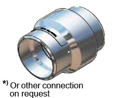
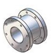
Swivel Joints are used in the industry wherever a movable pipe-connection system between two equipment parts is needed. Avoiding one of the biggest causes of premature hose failure. Torque stress is the largest single cause of PTFE and Stainless steel convoluted hose failure.
The swivel joints are designed for slow rotary motions under the influence of high internal pressures and/or external stress such as traction and bending forces.
With an appropriate combination of swivel joints nearly all movements from the simple rotation or swivelling motion up to motional actions in space can be realized.
| Company information and introduction | 2 |
| Hose Swivels - single ball bearing | 3-4 |
| Heavy Duty Swivels - double ball race | 5-6 |
| How to order Swivels | 7 |
| Flange facing types according to EN 1092 | 8 |
| Flange Measurement | 9-10 |
| Flange connection | 11 |
| About NPT and BSP threads | 12 |
| Flat Seals for thread | 13 |
| Flat Seals for thread | 14 |
| O-ring materials | 15 |
| Other leaflets and contact information | 16 |
The use of hose swivel avoids torsion of hose assemblies, i.e. in filling machines, and improves the handling and coupling of nozzles for refuelling of petroleum based products and chemicals.


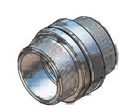
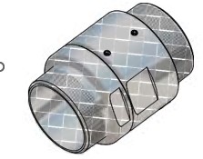
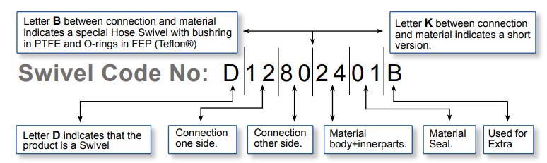
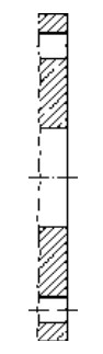
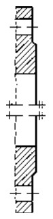
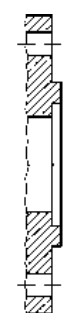
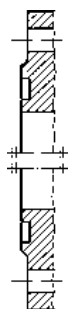
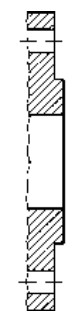
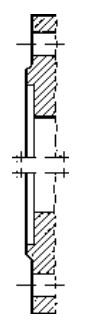
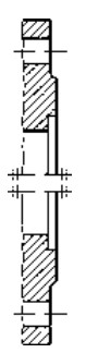
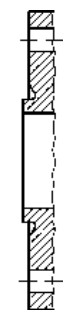
The diagram shows the internal construction of the Mann Tek standard Hose Swivel, with the following components:
| Swivel sizes | |||||||
|---|---|---|---|---|---|---|---|
| 3/4" | 1" | 1 1/4" | 1 1/2" | 2" | 2 1/2" | 3" | 4" |
| Threads (Female / Male1)) |
|---|
| BSP (ISO 228) |
| NPT (ASME/ANSI 1.20.1) |
| BSPT (EN 10226) |
| ACME |
| Weld end |
| Flanges |
|---|
| DIN Flange (ISO 1092 PN 10/16, PN 25/40 (Type A, B, E, F 2))) |
| ASA Flange (ASME/ANSI 16.5) |
| TW-Flange (DIN 28459) |
| T.T.M.A |
1) Any combinations of male and female threads is possible. 2) See page 14 for illustrations of different types of DIN-flanges
| Standard Materials and standard Seals | |||||
|---|---|---|---|---|---|
| Component | Material | Material Standard | Operation temp | O-ring | Flat Seal |
| Body | Aluminium | EN 755 - AW-6262-T6 | -40°C to 250°C | FPM/KFM (Viton®) |
PUR (Vulkollan®) |
| EN 1706-AC-42100-T6 | |||||
| Brass | EN 12164 - CW614N EN 1982 - CB491K-GS |
PUR (Vulkollan®) | |||
| Stainless Steel | EN 10272 - 1.4404+AT | PTFE (Teflon®) | |||
| EN 10213 - 1.4409+AT | |||||
Working Pressure: (10 bar) - 300 psi (20 bar)
We manufacture Swivels in different sizes, connections and materials on request!
| One side | Other side | One side | Other side | One side | Other side | |||
| BSP/NPT Female | BSP/NPT Female | BSP/NPT Female | BSP/NPT Male | BSP/NPT Male | BSP/NPT Male |
 |
 |
 |
|||
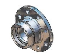
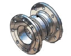
| One side | Other side | One side | Other side | One side | Other side | |||
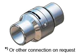
| BSP/NPT Thread | Flange | Flange | Flange | Weld end | Weld end *) |
 |
 |
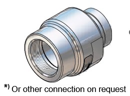
 *) Or other connection on request |
|||
Viton® and Teflon® are registered trademarks of DuPont, DuPont Elastomers. Vulkollan® is registered trademark of Bayer AG
The swivel Heavy duty is designed especially for hose rails to load and unload products like Aliphatic and Aromatic hydrocarbons, Alcohols and Amines, Ether and Ester, Glycos and Water, Liquid Fertilizers, Acids and Lyes.


| Swivel sizes | ||||||
|---|---|---|---|---|---|---|
| 2" | 3" | 4" | 5" | 6" | 8" | 10" |
| Threads (Female / Male1)) |
|---|
| BSP (ISO 228) |
| NPT (ASME/ANSI 1.20.1) |
| BSPT (EN 10226) |
| ACME |
| Victaulic |
| Weld end |
| Flanges |
|---|
| DIN Flange (ISO 1092 PN 10/16, PN 25/40 (Type A, B, E, F 2))) |
| ASA Flange 150 psi / 300 psi (ASME/ANSI 16.5) |
| TW-Flange (DIN 28459) |
| T.T.M.A |
1) Any combinations of male and female threads is possible. 2) See page 14 for illustrations of different types of DIN-flanges
| Standard Materials and standard Seals | |||||
|---|---|---|---|---|---|
| Component | Material | Material Standard | Operation temp | Seal | Flat Seal |
| Body | Aluminium | EN 755 - AW-6262-T6 | -100°C to 250°C | PTFE (Teflon®) |
PUR (Vulkollan®) |
| EN 1706-AC-42100-T6 | |||||
| Stainless Steel | EN 10272 - 1.4404+AT EN 10213 - 1.4409+AT |
PTFE (Teflon®) | |||
Working Pressure: 150 psi (10 bar) - 1800 psi (125 bar)
We manufacture Swivels in different sizes, connections and materials on request!
| One side | Other side | One side | Other side | One side | Other side | One side | Other side | ||||
| BSP/NPT F | BSP/NPT F | BSP/NPT F | BSP/NPT M | BSP/NPT M | BSP/NPT M | Thread | Flange |
 |
 |
 |
 |
||||
| One side | Other side | One side | Other side | One side | Other side | |||||
| Flange | Flange | Victaulic | Victaulic *) | Weld end | Weld end *) | Compact version | |
 |
 *) Or other connection on request |
 *) Or other connection on request |
 |
||||
Viton® and Teflon® are registered trademarks of DuPont, DuPont Elastomers. Vulkollan® is registered trademark of Bayer AG
Letter D indicates that the product is a Swivel
04 = 1" NPT (Female)
05 = 1¼" BSP (Female)
06 = 1¼" NPT (Female)
07 = 1½" BSP (Female)
08 = 1½" NPT (Female)
09 = 1¾" BSP (Female)
10 = 2" BSP (Female)
11 = 2" NPT (Female)
12 = 2½" BSP (Female)
13 = 2½" NPT (Female)
14 = 3" BSP (Female)
15 = 3" NPT (Female)
16 = 4" BSP (Female)
17 = 4" NPT (Female)
18 = Flange undrilled Ø156
19 = Flange undrilled Ø165
20 = Flange undrilled Ø210
21 = Flange undrilled Ø230
22 = Flange undrilled Ø254
23 = Flange DN 25 PN 10/16
24 = Flange DN 32 PN 10/16
25 = Flange DN 25 PN 25/40
26 = Flange DN 32 PN 25/40
27 = Flange DN 40 PN 10/16
28 = Flange DN 50 PN 25/40
29 = Flange DN 40 PN 25/40
30 = Flange DN 50 PN 10/16
31 = Flange DN 50 PN 25/40
32 = Flange DN 65 PN 10/16
33 = Flange DN 65 PN 25/40
34 = Flange DN 80 PN 10/16
35 = Flange DN 80 PN 25/40
36 = Flange DN 80 PN 40
37 = Flange DN 80 PN 25
38 = Flange DN 100 PN 10/16
39 = Flange DN 100 PN 25/40
40 = Flange DN 100 PN 25
41 = Flange DN 100 PN 200
42 = Flange DN 125 PN 10/16
43 = Flange DN 125 PN 25/40
44 = Flange DN 150 PN 10/16
45 = Flange DN 150 PN 25/40
46 = Flange DN 150 PN 25
47 = Flange DN 200 PN 10/16
48 = Flange DN 20 PN 10/16
49 = Flange DN 20 PN 25/40
50 = Flange ½" ANSI Class 150
51 = Flange 1" ANSI Class 150
52 = Flange 1" ANSI Class 300
53 = Flange 1¼" ANSI Class 150
54 = Flange 1¼" ANSI Class 300
55 = Flange 1½" ANSI Class 150
56 = Flange 1½" ANSI Class 300
57 = Flange 2" ANSI Class 150
58 = Flange 2" ANSI Class 300
59 = Flange 2½" ANSI Class 150
60 = Flange 2½" ANSI Class 300
61 = Flange 3" ANSI Class 150
62 = Flange 3" ANSI Class 300
63 = Flange 4" ANSI Class 150
64 = Flange 4" ANSI Class 300
65 = Flange TW 1 (3" DN 80)
66 = Flange TW 1 (4" DN 100)
67 = Flange TW 1 (1¼" DN 32)
68 = Flange 4" T.T.M.A
69 = Flange 5" ANSI Class 150
70 = ¾" NPT (Female)
71 = 1" BSP (Male)
75 = 1½" BSP (Male)
76 = 1½" NPT (Male)
77 = 1¾" BSP (Male)
78 = 2" BSP (Male)
79 = 2" NPT (Male)
80 = 2½" BSP (Male)
81 = 2½" NPT (Male)
82 = 3" BSP (Male)
83 = 3" NPT (Male)
84 = 4" BSP (Male)
85 = 4" NPT (Male)
86 = Weld.flange 2" Ø60.5 inner
87 = Flange TW 1 (2" DN50)
88 = Weld.flange 2" Ø50-Ø70 (flat)
89 = Weld.flange 2" Ø57 (int. chamfer)
90 = Weld.flange 2" Ø60 (outer chamfer)
91 = Weld.flange 3" Ø75-Ø90 (flat)
92 = Weld.flange 3" Ø76 (int. chamfer)
93 = Weld.flange 3" Ø89 (outer. chamfer)
94 = Weld.flange 4" Ø100-Ø120 (flat)
95 = Weld.flange 4" Ø102 (int. chamfer)
96 = Weld.flange 4" Ø108 (int. chamfer)
97 = Weld.flange 4" Ø114 (outer. chamfer)
98 = Flange TW 1 (2" DN 50)
99 = Flange 6" ANSI Class 150
100 = Flange 6" ANSI Class 150
101 = Flange 6" ANSI Class 300
102 = Flange 8" ANSI Class 150
103 = Flange DN 200 PN 16
104 = Flange DN 200 PN 25
105 = Flange 8" ANSI Class 150
106 = Flange 8" ANSI Class 300
107 = Flange Square ISO 45
108 = 56tlot (Female)
109 = 60tlot (Male)
110 = 6" BSP (Female)
111 = 6" NPT (Female)
112 = ¾" W2" 7 (Female)
113 = Weld.flange 3" Ø92 inner
114 = Square flange, 4 holes
115 = 6" BSP (Male)
116 = 6" NPT (Male)
117 = 8" NPT (Female)
118 = 4" Victaulic
119 = Flange DN 50 PN 25/40
120 = Flange DN 80 PN 25/40
121 = Flange DN 100 PN 25/40
122 = Flange DN 80 PN 25/40
123 = W2" 7 (Male)
124 = 5" NPT (Female)
125 = 5" NPT (Male)
126 = Flange DN 100 PN6
127 = Flange DN 80 PN6
128 = Flange DN 65 PN6
129 = ¾" NPT (Female)
130 = Flange 8" ANSI Class 600
131 = W90x1/6" (Female)
132 = ½" NPT (Male)
133 = ½" BSP (Female)
134 = Flange ø184, 2 E holes
135 = Flange TW (7" DN 150)
136 = 4" ASPT (Female)
137 = Triclamp DN 25
138 = M54x1.5 (Female)
139 = Triclamp (ISO 2852-51)
140 = Weld.flange Ø73 (outer chamfer)
141 = 3" Victaulic
142 = Flange 5" ANSI Class 150
143 = 3" Ball valve
151 = Flange 1" DIN 11864-2
152 = Flange 2" DIN 11864-2
153 = Flange ø135, 8xM6
154 = 4" BSPT (Female)
155 = 4" BSPT (Male)
156 = Weld flange 2" ø61.5 (inner)
157 = 3" BSPT (Female)
158 = Weld end 1½" ø48 (outer)
159 = Thread TR 57x4
160 = Flange 2" BS10 Table D
161 = Flange 12" ANSI Class 150
162 = Flange 10" ANSI Class 150
163 = Flange DN 250 PN 16
164 = M130x6 (Female)
165 = Flange 10" ANSI Class 300
166 = ACME 1¼" (Female)
167 = ACME 1¾" (Female)
168 = ACME 2¼" (Female)
169 = ACME 3¼" (Female)
170 = ACME 2½" (Male)
171 = ACME 1¼" (Male)
172 = ACME 2½" (Male)
173 = ACME 3½" (Male)
174 = Weld.flange Ø76 (outer. chamfer)
175 = Flange DN 15 PN 10/16
176 = Flange DN 15 PN 25/40
177 = M130x6 (Male)
178 = Flange 6" T.T.M.A
179 = Flange DN 80 PN 25/40***
180 = ½" NPT (Male)
181 = ½" BSP (Male)
182 = 5" BSP (Female)
183 = 5" BSP (Male)
184 = Weld end ø8219 (outer)
185 = Weld end 6" 6168 (outer)
186 = 5" BSP (Female) 08
187 = Weld.flange 3" Ø92 inner
188 = Flange 12" BS16 Class 300
189 = Flange ½" ANSI Class 150
190 = Flange 1" ANSI Class 150 Flat Face
191 = Flange 12" ANSI Class 300
192 = Flange DN250 PN10
193 = Weld end Ø114 Schedule 40
194 = Weld end Ø114 Schedule 80
195 = 6" Victaulic
196 = 1" Victaulic
197 = DN 120 JIS 5K
198 = DN 40 JIS 5K
199 = DN 80 JIS 5K
200 = DN 50 JIS 5K
201 = DN 40 JIS 5K
202 = Flange 2" DIN 11864-3
203 = 3½" BSP (Female)
204 = Flange Ø110, Ø86/0.5 (6x)
205 = Weld end Ø60 Schedule 80
206 = Weld end Ø60 Schedule 40
207 = Weld end Ø114 Schedule 40
208 = Flange DN 29 PN 6
209 = Flange DN 32 PN 6
210 = Flange DN 40 PN 6
211 = DN 125 JIS 10K
212 = DN 100 JIS 10K
213 = DN 80 JIS 10K
214 = DN 50 JIS 10K
215 = DN 40 JIS 10K
216 = Flange DN 80, holes Ø14 (6x)
217 = Flange DN 200 PN 40 PN 6
218 = Triclamp (ISO 2852-76)
| 1 = Aluminium | 3 = Steel |
| 2 = Brass | 4 = Stainless steel A |
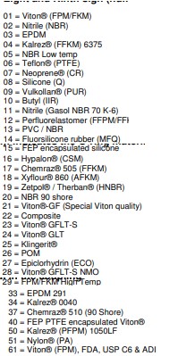
| 01 = Viton® (FPM/FKM) | 16 = Hypalon® (CSM) |
| 02 = Nitrile (NBR) | 17 = Chemraz® 505 (FFKM) |
| 03 = EPDM | 18 = Xyfour® 860 (AFKM) |
| 04 = Kalrez® (FFKM) 6375 | 19 = Zetpol® / Therban® (HNBR) |
| 05 = NBR Low temp | 20 = NBR 90 shore |
| 06 = Teflon® (PTFE) | 21 = Viton®-GF (Special Viton quality) |
| 07 = Neoprene® (CR) | 22 = Composite |
| 08 = Silicone (Q) | 23 = Viton® GFLT-S |
| 09 = Vulkollan® (PUR) | 24 = Viton® GLT |
| 10 = Butyl (IIR) | 25 = Klingersit® |
| 11 = Nitrile (Gasol NBR 70 K-6) | 26 = POM |
| 12 = Perfluoroelastomer (FFPM/FF) | 27 = Epiclorhydrin (ECO) |
| 13 = PVC / NBR | 28 = Viton® GFLT-S NMO |
| 14 = Fluorsilicone rubber (MFQ) | 29 = FPM/FKM Higt*Temp |
| 15 = FEP encapsulated silicone | 33 = EPDM 291 |
| 34 = Kalrez® 0040 | |
| 37 = Chemraz® 510 (90 Shore) | |
| 40 = FEP PTFE encapsulated Viton® | |
| 50 = Kalrez® (PFPM) 1050LF | |
| 51 = Nylon® (PA) | |
| 61 = FPM (FPM), FDA, USP C6 & ADI |
| A = Flat Seal, PTFE (Teflon®) |
| B = Flat Seal PUR (Vulkollan®) |
| D = Flat Seal FPM (Viton®) |
| W = Double Ball Race |
E.G. Code No: D10794401A = Hose Swivel, Single ball bearing
One side: 2" BSP (Female) Other side: 2" NPT (Male)
Material: Stainless Steel, Flat Seal PTFE (Teflon®)
E.G. Code No: D85614401W = Swivel, Double ball race
One side: 4" NPT (Male) Other side: Flange 3", ANSI (ASA) 150 psi
Material: Stainless Steel

| Type A | Type B | Type C | Type D |
|---|---|---|---|
| Flat face | Raised face | Tongue | Groove |
| Type E | Type F | Type G | Type G |
| Spigot | Recess | O-ring Spigot | O-ring Groove |

Ø D = Diameter
Ø k = Centre diameter
n = Number of holes
Ø d = Hole diameter
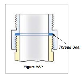
| EN 1092-1 | |||||||||||||||||
|---|---|---|---|---|---|---|---|---|---|---|---|---|---|---|---|---|---|
| DN | PN 10 | PN 16 | PN 25 | PN 40 | |||||||||||||
| ØD | Øk | n | Ød | ØD | Øk | n | Ød | ØD | Øk | n | Ød | ØD | Øk | n | Ød | ||
| 20 | mm | 105 | 75 | 4 | 14 | 105 | 75 | 4 | 14 | 105 | 75 | 4 | 14 | 105 | 75 | 4 | 14 |
| inch | 4.13 | 2.95 | 0.55 | 4.13 | 2.95 | 0.55 | 4.13 | 2.95 | 0.55 | 4.13 | 2.95 | 0.55 | |||||
| 25 | mm | 115 | 85 | 4 | 14 | 115 | 85 | 4 | 14 | 115 | 85 | 4 | 14 | 115 | 85 | 4 | 14 |
| inch | 4.53 | 3.35 | 0.55 | 4.53 | 3.35 | 0.55 | 4.53 | 3.35 | 0.55 | 4.53 | 3.35 | 0.55 | |||||
| 32 | mm | 140 | 100 | 4 | 18 | 140 | 100 | 4 | 18 | 140 | 100 | 4 | 18 | 140 | 100 | 4 | 18 |
| inch | 5.51 | 3.94 | 0.71 | 5.51 | 3.94 | 0.71 | 5.51 | 3.94 | 0.71 | 5.51 | 3.94 | 0.71 | |||||
| 40 | mm | 150 | 110 | 4 | 18 | 150 | 110 | 4 | 18 | 150 | 110 | 4 | 18 | 150 | 110 | 4 | 18 |
| inch | 5.91 | 4.33 | 0.71 | 5.91 | 4.33 | 0.71 | 5.91 | 4.33 | 0.71 | 5.91 | 4.33 | 0.71 | |||||
| 50 | mm | 165 | 125 | 4 | 18 | 165 | 125 | 4 | 18 | 165 | 125 | 4 | 18 | 165 | 125 | 4 | 18 |
| inch | 6.50 | 4.92 | 0.71 | 6.50 | 4.92 | 0.71 | 6.50 | 4.92 | 0.71 | 6.50 | 4.92 | 0.71 | |||||
| 65 | mm | 185 | 145 | 4 | 18 | 185 | 145 | 4 | 18 | 185 | 145 | 8 | 18 | 185 | 145 | 8 | 18 |
| inch | 7.28 | 5.71 | 0.71 | 7.28 | 5.71 | 0.71 | 7.28 | 5.71 | 0.71 | 7.28 | 5.71 | 0.71 | |||||
| 80 | mm | 200 | 160 | 8 | 18 | 200 | 160 | 8 | 18 | 200 | 160 | 8 | 18 | 200 | 160 | 8 | 18 |
| inch | 7.87 | 6.30 | 0.71 | 7.87 | 6.30 | 0.71 | 7.87 | 6.30 | 0.71 | 7.87 | 6.30 | 0.71 | |||||
| 100 | mm | 220 | 180 | 8 | 18 | 220 | 180 | 8 | 18 | 235 | 190 | 8 | 22 | 235 | 190 | 8 | 22 |
| inch | 8.66 | 7.09 | 0.71 | 8.66 | 7.09 | 0.71 | 9.25 | 7.48 | 0.87 | 9.25 | 7.48 | 0.87 | |||||
| 125 | mm | 250 | 210 | 8 | 18 | 250 | 210 | 8 | 18 | 270 | 220 | 8 | 26 | 270 | 220 | 8 | 26 |
| inch | 9.84 | 8.27 | 0.71 | 9.84 | 8.27 | 0.71 | 10.63 | 8.66 | 1.02 | 10.63 | 8.66 | 1.02 | |||||
| 150 | mm | 285 | 240 | 8 | 22 | 285 | 240 | 8 | 22 | 300 | 250 | 8 | 26 | 300 | 250 | 8 | 26 |
| inch | 11.22 | 9.45 | 0.87 | 11.22 | 9.45 | 0.87 | 11.81 | 9.84 | 1.02 | 11.81 | 9.84 | 1.02 | |||||
| 200 | mm | 340 | 295 | 8 | 22 | 340 | 295 | 12 | 22 | 360 | 310 | 12 | 26 | 375 | 320 | 12 | 30 |
| inch | 13.39 | 11.61 | 0.87 | 13.39 | 11.61 | 0.87 | 14.17 | 12.20 | 1.02 | 14.76 | 12.60 | 1.18 | |||||
| 250 | mm | 395 | 355 | 12 | 22 | 405 | 355 | 12 | 26 | 425 | 370 | 12 | 30 | 450 | 385 | 12 | 33 |
| inch | 15.55 | 13.98 | 0.87 | 15.94 | 13.98 | 1.02 | 16.73 | 14.57 | 1.18 | 17.72 | 15.16 | 1.30 | |||||
| 300 | mm | 445 | 400 | 12 | 22 | 460 | 410 | 12 | 26 | 485 | 430 | 16 | 30 | 515 | 450 | 16 | 33 |
| inch | 17.52 | 15.75 | 0.87 | 18.11 | 16.14 | 1.02 | 19.09 | 16.93 | 1.18 | 20.28 | 17.65 | 1.30 | |||||
| EN 1092-1 | DIN |
|---|---|
| EN 1092-1 PN 6 | DIN 2631 |
| EN 1092-1 PN 10 | DIN 2632 |
| EN 1092-1 PN 16 | DIN 2633 |
| EN 1092-1 PN 25 | DIN 2634 |
| EN 1092-1 PN 40 | DIN 2635 |
| EN 1092-1 Type B Raised Face | DIN 2526 Form C |
| EN 1092-1 Type C Tongue | DIN 2512 Form F |
| EN 1092-1 Type D Groove | DIN 2512 Form N |
| EN 1092-1 Type E Spigot | DIN 2513 Form V |
| EN 1092-1 Type F Recess | DIN 2513 Form R |

Ø D = Diameter
Ø k = Centre diameter
n = Number of holes
Ø d = Hole diameter
| ANSI (ASA) B 16,5 | |||||||||
|---|---|---|---|---|---|---|---|---|---|
| INCH | 150 psi | 300 psi | |||||||
| ØD | Øk | n | Ød | ØD | Øk | n | Ød | ||
| 3/4" | mm | 98,4 | 69,8 | 4 | 15,9 | 117,5 | 82,5 | 4 | 19 |
| inch | 3⅞ | 2¾ | ⅝ | 4⅝ | 3¼ | ¾ | |||
| 1" | mm | 107,7 | 79,4 | 4 | 15,9 | 123,8 | 88,9 | 4 | 19 |
| inch | 4¼ | 3⅛ | ⅝ | 4⅞ | 3½ | ¾ | |||
| 1 1/4" | mm | 117,5 | 88,9 | 4 | 15,9 | 133,3 | 98,4 | 4 | 19 |
| inch | 4⅝ | 3½ | ⅝ | 5¼ | 3⅞ | ¾ | |||
| 1 1/2" | mm | 127 | 98,4 | 4 | 15,9 | 155,6 | 114,3 | 4 | 22,2 |
| inch | 5 | 3⅞ | ⅝ | 6⅛ | 4½ | ⅞ | |||
| 2" | mm | 152,4 | 120,6 | 4 | 19 | 165,1 | 127 | 8 | 19 |
| inch | 6 | 4¾ | ¾ | 6½ | 5 | ¾ | |||
| 2 1/2" | mm | 177,8 | 139,7 | 4 | 19 | 190,5 | 149,2 | 8 | 22,2 |
| inch | 7 | 5½ | ¾ | 7½ | 5⅞ | ⅞ | |||
| 3" | mm | 190,5 | 152,4 | 4 | 19 | 209,5 | 168,3 | 8 | 22,2 |
| inch | 7½ | 6 | ¾ | 8¼ | 6⅝ | ⅞ | |||
| 4" | mm | 228,5 | 190,5 | 8 | 19 | 254 | 200 | 8 | 22,2 |
| inch | 9 | 7½ | ¾ | 10 | 7⅞ | ⅞ | |||
| 5" | mm | 254 | 215,9 | 8 | 22,2 | 279,4 | 234,9 | 8 | 22,2 |
| inch | 10 | 8½ | ⅞ | 11 | 9¼ | ⅞ | |||
| 6" | mm | 279,4 | 241,3 | 8 | 22,2 | 317,5 | 269,9 | 12 | 22,2 |
| inch | 11 | 9½ | ⅞ | 12½ | 10⅝ | ⅞ | |||
| 8" | mm | 342,9 | 298,4 | 8 | 22,2 | 381 | 330,2 | 12 | 25,4 |
| inch | 13½ | 11¾ | ⅞ | 15 | 13 | 1 | |||
| 10" | mm | 406,4 | 361,9 | 12 | 25,4 | 444,5 | 387,3 | 16 | 28,6 |
| inch | 16 | 14¼ | 1 | 17½ | 15¼ | 1⅛ | |||
| 12" | mm | 482,6 | 431,8 | 12 | 25,4 | 520,7 | 450,8 | 16 | 31,7 |
| inch | 19 | 17 | 1 | 20½ | 17¾ | 1¼ | |||
| TW DIN 28459 | |||||
|---|---|---|---|---|---|
| DN | ØD | Øk | n | Ød | |
| TW1 50 | mm | 154 | 130 | 8 | 11 |
| inch | 6.06 | 5.12 | 0.43 | ||
| TW1 80 | mm | 154 | 130 | 8 | 11 |
| inch | 6.06 | 5.12 | 0.43 | ||
| TW3 100 | mm | 174 | 150 | 8 | 14 |
| inch | 6.85 | 5.91 | 0.55 | ||
| TW5 125 | mm | 204 | 176 | 8 | 14 |
| inch | 8.03 | 6.93 | 0.55 | ||
| TW7 150 | mm | 240 | 210 | 12 | 14 |
| inch | 9.45 | 8.27 | 0.55 | ||
| T.T.M.A | |||||
|---|---|---|---|---|---|
| INCH | ØD | Øk | n | Ød | |
| 2" | mm | 114,3 | 95,3 | 6 | 11,1 |
| inch | 4.50 | 3.75 | 0.44 | ||
| 3" | mm | 142,9 | 123,8 | 8 | 11,1 |
| inch | 5.63 | 4.87 | 0.44 | ||
| 4" | mm | 168,3 | 149,2 | 8 | 11,1 |
| inch | 6.63 | 5.87 | 0.44 | ||
| 5" | mm | 196,9 | 177,8 | 12 | 11,1 |
| inch | 7.75 | 7.00 | 0.44 | ||
| 6" | mm | 228,6 | 206,4 | 12 | 11,1 |
| inch | 9.00 | 8.13 | 0.44 | ||
| 8" | mm | 276,2 | 257,2 | 16 | 11,1 |
| inch | 10.87 | 10.13 | 0.44 | ||
The Mann-Tek product can be installed directly in the product line and is ready for use after removing the transport protection. The installation is recommended as follows:
| Metric | |
|---|---|
| Size | 8.8 |
| M8 | 24 Nm |
| M10 | 50 Nm |
| M12 | 85 Nm |
| M16 | 210 Nm |
| M20 | 410 Nm |
| M22 | 550 Nm |
| M24 | 700 Nm |
| Inch — A193 B7 | |
|---|---|
| Size | A193 B7 |
| 5/16 -18 UNC | 16 lbf-ft |
| 3/8 -16 UNC | 29 lbf-ft |
| 1/2 -13 UNC | 70 lbf-ft |
| 5/8 -11 UNC | 139 lbf-ft |
| 3/4 -10 UNC | 243 lbf-ft |
| 7/8 -9 UNC | 389 lbf-ft |
| 1 -8 UNC | 582 lbf-ft |
g. Bolt tightening sequence.

The start-up may take place only when the Mann-Tek product has been mounted as instructed and the necessary function tests and leak tests have been conducted by the approved authorities.
1) The torque forces recommended bases on a thread friction coefficient μ=0,14 and a standard flat seal according to EN 1514-1
Sealing NPT threads can be an exasperating experience if certain techniques are not followed. The following tips will help alleviate many common problems in thread sealing:
1. Always use some type of sealant (tape or paste) and apply sealant to male thread only. If using a hydraulic sealant, allow sufficient curing time before system is pressurized.
2. When using tape sealant, wrap the threads in a clockwise motion starting at the first thread and, as layers are applied, work towards the imperfect (vanishing) thread. If the system that the connection being made to cannot tolerate foreign matter (i.e. air systems), leave the first thread exposed and apply the tape sealant as outlined above.
3. When using paste sealant, apply to threads with a brush, using the brush to work the sealant into the threads. Apply enough sealant to fill in all the threads all the way around.
4. When connecting one stainless steel part to another stainless steel part that will require future disassembly, use a thread sealant that is designed for stainless steel. This stainless steel thread sealant is also useful when connecting aluminium to aluminium that needs to be disconnected in the future. These two materials gall easily, and if the correct sealant is not used, it can be next to impossible to disassemble.
5. When connecting parts made of dissimilar metals (i.e. steel and aluminium), standard tape or paste sealant performs satisfactory.
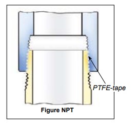
6. For sizes 2" and below, tape or paste performs satisfactory. When using thread tape, four wraps (covering all necessary threads) is usually sufficient.
7. For sizes 2½" and above, thread paste is recommended. If thread tape is used, eight wraps (covering all necessary threads) is usually sufficient. Apply more wraps if necessary.

Figure NPT — PTFE-tape
8. For stubborn to seal threads, apply a normal coating of thread paste followed by a normal layer of thread tape.
9. For extremely stubborn to seal threads, apply a normal coating of thread paste followed by a single layer of gauze bandage followed by a normal layer of thread tape.
Caution!
When this procedure is done, the connection becomes permanent. Extreme measures will be necessary to disconnect these components. All other measures to seal the threads should be explored prior to use of this technique.
10. Over-tightening threads can be just as detrimental as insufficient tightening. For sizes 2" and below, hand tighten the components and, with a wrench, tighten 3 full turns. For sizes 2½" and above, hand tighten the components and, with a wrench, tighten 2 full turns.
This allows to use the full thread length for screwed-on parts. The largest possible transfer of force is guaranteed for short length. The thread seal behind the relief groove of the thread cannot drop out.
Simple screwing down, makes a safe connection. Subsequent tightening during operation is possible at any time. Change of seal and new assembly do not require any expert knowledge.
The European standardisations for hose assemblies require parallel threads with flat seals, because of the advantages.

Figure BSP — Thread Seal
| weight ≈kg | Thread BSP | Materials / Application | D | d | s | Product No |
|---|---|---|---|---|---|---|
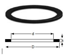
| 0,001 | BSP ½" | PTFE (Teflon®) white, massive continuously hard, universally resistant Teflon® is a registered trademark of DuPont | 20 | 13 | 2 | On request |
| 0,001 | BSP ¾" | 26 | 19 | 2 | 1498-06 | |
| 0,002 | BSP 1" | 33 | 24 | 2 | 1220-06 | |
| 0,003 | BSP 1 ¼" | 42 | 34 | 2 | 1536-06 | |
| 0,003 | BSP 1 ½" | 48 | 39 | 2 | 1196-06 | |
| 0,004 | BSP 2" | 60 | 49 | 2 | 1052-06 | |
| 0,007 | BSP 2 ½" | 76 | 63 | 2,5 | 1181-06 | |
| 0,006 | BSP 3" | 88 | 77 | 3 | 1110-06 | |
| 0,009 | BSP 4" | 114 | 100 | 3 | 1295-06 | |
| 0,016 | BSP 6" | 164 | 150 | 3 | 1963-06 | |
| 0,001 | BSP ½" | Thermopac asbestos free, light hard. Especially for hot oils and hot bitumen up to 250°C and for hot water and saturated steam up to 25 bar. | 20 | 13 | 2 | On request |
| 0,001 | BSP ¾" | 26 | 19 | 2 | 1498-25 | |
| 0,002 | BSP 1" | 33 | 24 | 2 | 1220-25 | |
| 0,002 | BSP 1 ¼" | 42 | 34 | 2 | 1536-25 | |
| 0,003 | BSP 1 ½" | 48 | 39 | 2 | 1196-25 | |
| 0,004 | BSP 2" | 60 | 49 | 2 | 1052-25 | |
| 0,005 | BSP 2 ½" | 76 | 63 | 3 | 1181-25 | |
| 0,009 | BSP 3" | 88 | 77 | 3 | 1110-25 | |
| 0,013 | BSP 4" | 114 | 100 | 3 | 1295-25 | |
| 0,016 | BSP 6" | 164 | 150 | 3 | 1963-25 | |
| 0,001 | BSP ½" | FPM/FKM (Viton®) soft for aromatic hydrocarbons and hot oils. Viton® is a registered trademark of DuPont | 20 | 13 | 2 | On request |
| 0,001 | BSP ¾" | 26 | 19 | 2 | 1498-01 | |
| 0,002 | BSP 1" | 33 | 24 | 2 | 1220-01 | |
| 0,002 | BSP 1 ¼" | 42 | 34 | 2 | 1536-01 | |
| 0,003 | BSP 1 ½" | 48 | 39 | 2 | 1196-01 | |
| 0,004 | BSP 2" | 60 | 49 | 2 | 1052-01 | |
| 0,006 | BSP 2 ½" | 76 | 63 | 3 | 1181-01 | |
| 0,008 | BSP 3" | 88 | 77 | 3 | 1110-01 | |
| 0,014 | BSP 4" | 114 | 100 | 3 | 1295-01 | |
| 0,016 | BSP 6" | 164 | 150 | 3 | 1963-01 | |
| 0,001 | BSP ¾" | PUR (Vulkollan®) Flat seals type of polyurethane, hightly resitant to abrasion, non-toxic. Shore hardness=90°. For all petroleum based products and many solvents. Colour: Blue Vulkollan® is a registered trademark of Bayer | 26 | 19 | 2 | 1498-09 |
| 0,001 | BSP 1" | 33 | 24 | 2 | 1220-09 | |
| 0,001 | BSP 1 ¼" | 42 | 34 | 2 | 1536-09 | |
| 0,002 | BSP 1 ½" | 48 | 39 | 2 | 1196-09 | |
| 0,003 | BSP 1 ¾" | 54 | 44 | 2,5 | On request | |
| 0,003 | BSP 2" | 60 | 49 | 2 | 1052-09 | |
| 0,005 | BSP 2 ½" | 76 | 63 | 2,5 | 1181-09 | |
| 0,006 | BSP 3" | 88 | 77 | 3 | 1110-09 | |
| 0,010 | BSP 3 ½" | 100 | 80 | 3 | On request | |
| 0,009 | BSP 4" | 114 | 100 | 3 | 1295-09 | |
| 0,012 | BSP 5" (No std) | 88 | 124 | 3 | On request | |
| 0,016 | BSP 6" | 164 | 150 | 3 | 1963-09 | |

| Flange Standard / Suitable for | Dimensions ≈ mm | Product No | ||||
|---|---|---|---|---|---|---|
| D | d | Øk | Øh | s | ||
| DN 25 PN 10/16 | 108 | 78,5 | 91 | 4 x 6,5 | 2 | - |
| DN 32 PN 10/16 | 140 | 43 | 100 | 4 x 18 | 2 | - |
| DN 50 PN 6 | 140 | 61 | 110 | 4 x 15 | 2 | - |
| DN 50 TW 1 | 154 | 50 | 130 | 8 x 12 | 2 | - |
| DN 80 TW 1 | 154 | 90 | 130 | 8 x 12 | 2 | - |
| DN 50 PN 10/16 | 165 | 61 | 125 | 4 x 18 | 2 | - |
| DN 100 TW3 | 174 | 110 | 150 | 8 x 14 | 2 | - |
| DN 65 PN 10/16 | 185 | 76 | 145 | 4 x 18 | 2 | - |
| DN 80 PN 10/16 | 200 | 90 | 160 | 8 x 18 | 2 | - |
| DN 125 TW5 | 204 | 135 | 176 | 8 x 14 | 2 | - |
| DN 100 PN 10/16 | 220 | 115 | 180 | 8 x 18 | 2 | - |
| DN 150 TW7 | 240 | 160 | 210 | 12 x 14 | 2 | - |
| DN 125 PN 10/16 | 250 | 141 | 210 | 8 x 18 | 2 | - |
| DN 150 PN 10/16 | 280 | 169 | 240 | 8 x 22 | 2 | - |
| DN 200 PN 10 | 340 | 220 | 295 | 8 x 22 | 2 | - |
| DN 200 PN 16 | 340 | 220 | 295 | 12 x 22 | 2 | - |
On request

ELAPAC-FD is a three component mixture, made of RUBBER (NBR) vulcanised, for the adhesion and resistance to kinking.
CORK for compressibility and sealing capability. When tightening the flange seal does not move towards the outer or inner edge of the sealing faces. The flange seal does not "settle," and can be re-used in most cases.
FIBRES give the material the necessary rigidity and the stability to insert flange seals into narrow gaps from the side. The values for swelling are considerably lower for fibre reinforced mixtures than for plain rubber seals.
Further advantages: No leaching out of softening agents. No shrinking or hardening through drying. No influence on or discoloration of media. No hardening at temperature range of -25 o up to +70o Celsius. No sticking on flange. Additional "adhesives" are not necessary. – Therefore good reusability.
The details refer to fitted flange seals. Only the inner rim of the flange seal is in contact with the medium. In the event of a possible attack this would only result in low penetration and the use is still possible. If the flange seal is completely immerged in the medium during laboratory tests, swelling and loss of stability is of course higher. If the resistance of ELAPAC is not sufficient but good compressibility is required, we offer the special design "TM" seal which is PTFE encapsulated.
Application of foodstuffs: ELAPAC-FD is only suitable with PTFE-cover, otherwise mixture particles can influence the quality of the foodstuffs.
APPLICATION: As an elastic flange seal for tank truck and tank plant construction etc., where rough sealing surfaces require a high adaptability, where flange seals should still have good flexibility to avoid pipe fractures or simple sealing materials because little or no force can be used to tighten the joint. Not suitable for use as thread seal, because the material is too soft and does not have enough lateral strength, this allows the medium to attack the seal material. Also not suitable for applications where the flange seal is only squashed on 2 mm to 3 mm of the total width. Care should be taken not to squash the material to much especially the 2 mm material, if in doubt please use the 3 mm material.
Due to the fibre content of ELAPAC; gas permeability is to be expected when using seals with narrow width – especially at high vacuum operation.
Approved as flange sealing material for all fuels and lubricants by the German military and the major oil companies for tank trucks, refineries and aircraft refuellers. Approved in 3 mm thickness by the German railway (Mat. No. 150.309). ELAPAC-FD meets the DIN 28 463.
| hardness, Shore | A 86 ± 3 |
| tensile strength | longitudinal 10 N/mm², lateral 4,5 N/mm² |
| elongation at break | longitudinal 15 N/mm², lateral 70 N/mm² |
| compressibility | 75 % |
| recovery | 90 % |
| compression set 24h, 70°C | 40 % |
| tear resistance | longitudinal 7 N/mm², lateral 10 N/mm² |
| working pressure maximal | 25 bar |
| colour | blue |
| marking | print ELAPAC-FD |
| Designation | Trade name | ISO 1629 | ASTM 1418 | Temp Range °C | Field of Application |
|---|---|---|---|---|---|
| Nitrile Butadiene Rubber | Buna N® Europrene N® Hycar® Nipol N® Perbunan N® |
NBR | NBR | -45 to 110 | Standard material for hydraulics and pneumatics. Mineral oil-based hydraulic fluids, animal and vegetable oils and fats. Flame retardant liquids. Aliphatic hydrocarbons (propane, butane, petrol). Silicone oils and greases. Water up to 80°C. Bio oils made from synthetic esters and vegetable oils |
| Ethylene-Propylene-Diene Rubber | Dutral Keltan® Vistalon® Buna AP® |
EPDM | EPDM | -55 to 120 | Hot water, vapour, brake fluids, detergents. Alcohols, ketons, engine coolants, flame retardant phosphate-based liquids, organic and inorganic acids and bases. Not resistent to mineral oils |
| Fluoroelastomer | Fluorel® Technoflon® Viton® |
FPM | FKM | -20 to 200 | Mineral oil and greases. Aliphatic, aromatic and chlorinated hydrocarbons, petrol, 99 octan petrol, diesel fuels, flame retardant phosphatebased liquids. Silicone oils and greases acids, lyes |
| Fluorosilicone Elastomer | - | MFQ | FVMQ | -60 to 200 | Mineral oils, fuels. lubricant on Di-Ester basis, hot air. |
| Silicone | Silastic® Silopren® |
MVQ | VMQ | -60 to 200 | Mineral oils, fuels. lubricant on Di-Ester basis, hot air. |
| Hydrogenated Nitrile-Butadiene Rubber | Therban® Tornac® Zetpol® |
HNBR** | HNBR** | -35 to 120 | Mineral oil-based hydralic fluids, animal and vegetable fats, aliphatic hydrocarbons, diesel fuels, ozone, sour gas, dilute acids and bases. Mineral oil-based hydralic fluids, animal and vegetable fats, aliphatic hydrocarbons, diesel fuels, ozone, sour gas, dilute acids and bases |
| Butyl Rubber | Exxon Butyl® Polysar Butyl® |
IIR | IIR | -55 to 100 | Butyl is a copolymer of isobutylene and isoprene. It has largely been replaced by ethylene propylene for O-ring usage. Butyl is resistant to the same fluid types as ethylenepropylene and except for resistance to gas permeation, it is somewhat inferior to ethylene-propylene for O-ring service. Excellent weather resistance, and gas permeation resistance. Poor petroleum oil and fuel resistance. |
| Perfluorinated Elastomer | CHEMRAZ® Kalrez® PERLAST® |
FFPM | FFPM | -40 to 260 | Best chemical resistance of all elastomers, including organic acids, f.i. acetic acid, benzoic acid, formic acid |
| Chloroprene Rubber | Baypren® Neoprene® |
CR | CR | -40 to 120 | Resistant to refrigerants, ammonia, carbon dioxide, freon(R12,R13,R21,R22,R113-R115). silicone oils, water, oxygen(low-pres.). bleaches, caustic soda, alcohols, chlorine, ozone, castor oil and veg. oils. Low resistance to mineral oils! |
| Polyester / Polyether Urethane Rubber | Adiprene® Urepan® Vulkollan® Desmopan® |
AU EU PUR |
AU EU |
-40 to 100 | Mineral oils and greases, oxygen, ozone. HFA and HFB fluids, air. Not resistant in esters, aliphatic, aromatic and chlorinated hydrocarbons, concentrated acids and lyes, water above +50°C. |
| Polytetrafluoroethylene | Teflon® | PTFE | PTFE | -200 to 260 | PTFE is used wherever the chemical and thermal resistance of the normal elastomer is no longer sufficient. These are primarily applications in the chemical industry, foodstuffs industry, pharmaceuticals and medical technology. PTFE are used only as static seals, e.g. on flange connections, on covers, etc. |
| Fluorinated Ethylene Propylene | Teflon FEP® | FEP/MVQ FEP/FPM |
FEP/VMQ FEP/FKM |
-60 to 200 -20 to 200 |
FEP is used wherever the chemical and thermal resistance of the normal elastomer is no longer sufficient. These are primarily applications in the chemical industry, foodstuffs industry, pharmaceuticals and medical technology. |
| Perflouralkoxy | Teflon PFA® | PFA/MVQ PFA/FPM |
PFA/VMQ PFA/FKM |
-60 to 250 -20 to 250 |
PFA is used wherever the chemical and thermal resistance of the normal elastomer is no longer sufficient. These are primarily applications in the chemical industry, foodstuffs industry, pharmaceuticals and medical technology. |
| Tetrafluoroethylene-Propylene Copolymer Elastomer | Aflas® | —— | TFE / P** | -25 to 200 | Mineral oils and greases, brake fluids, fuels, alcohols, heat transfer media, oils. amines, acids, bases |
Viton® (FPM) and Teflon® (FPM/KPM) are registered trademarks of DuPont, DuPont Elastomers. Vulkollan® is registered trademark of Bayer AG

Dry Disconnect Coupling. 1" to 8", PN 16 - PN 25. Aluminium, Brass-Gunmetal, Stainless Steel and PEEK. Other materials on request. According to NATO standard STANAG 3756.

Dry Gas Coupling. 1" to 8", PN25. Stainless steel. Other materials on request.

Dry Aviation Coupling. 2½", PN 10. Main body in Aluminium. Standards: ISO 45, MS 24484, NATO STANAG 3105, British Aerospace Spec. 2C14.

Stainless Steel SS-EN 10 088-1.4404+AT (AISI 316L). Ball Valve in 1.0619 and 1.4301

2" to 4", PN 10, Aluminium. Ballvalve and 2-way Ballvalve. Made for Petroleum Tank Trucks. Variations of flange connections.

¾" to 10", PN 10 - PN 25. Aluminium, Brass-Gunmetal, Stainless Steel. Other materials on request. Connection: BSP, NPT. Flanged connection (DIN, ANSI/ASA e.t.c)

Industrial and Marine Safety Break-away, breaking bolts, Aluminium, Brass, Stainless Steel, 1" to 12", female/male threads and with flanges, with breaking bolts.
Safety Break-away, cable release Stainless Steel, PN10 / PN 25. 2" to 4", female threads. 6" to 12", flanged connection
 Offshore & Marine |
 Gas (LPG) |
 Rail tankers |
 Chemical industry |
 Tank trucks |
 Military |
 Container |
 Cryogenic Couplings |

General Information about Mann Tek, products and Business Segments

Quality, Health, Safety and Environment Policy. Quality Approvals, Product Approvals and Declaration of Conformity
Service instructions and operation manuals
Didn't find the right Swivel Joints?
Fill in the form below, and we'll assist you further!
Curious about our blog? Check out all our items here!
Contact us here


 Nederlands
  Deutsch
  Français