Personal and expert advice
25 years of experience
Fast delivery times
Competitive prices
.jpg)
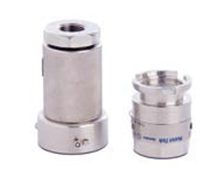
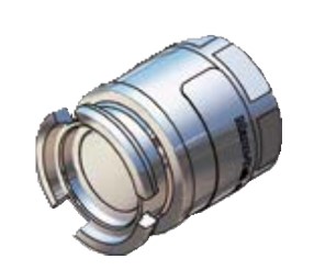
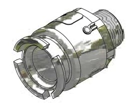
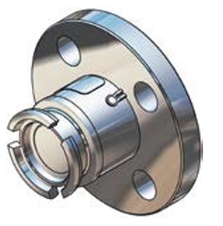
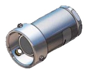
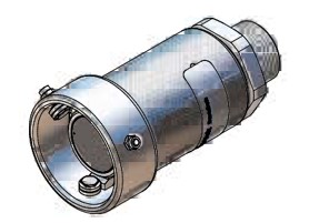
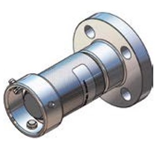
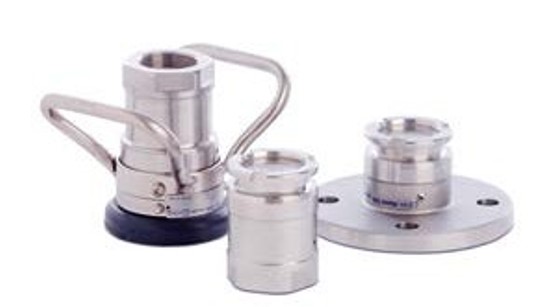
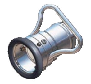
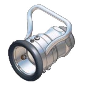
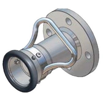
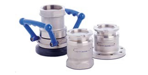
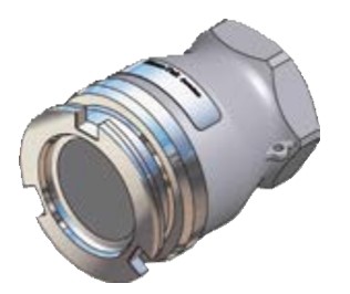
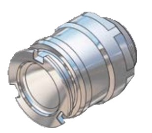
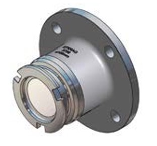
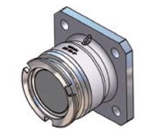
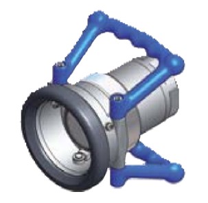
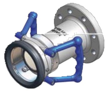
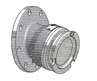
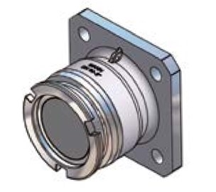
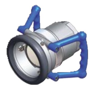
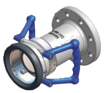
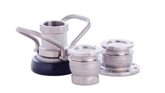
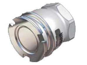
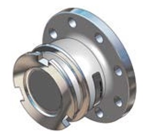
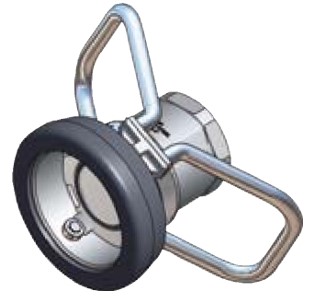
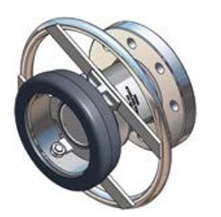
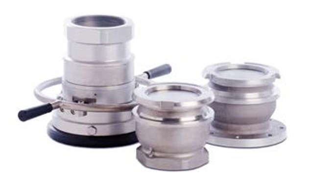
Dry Disconnect Couplings
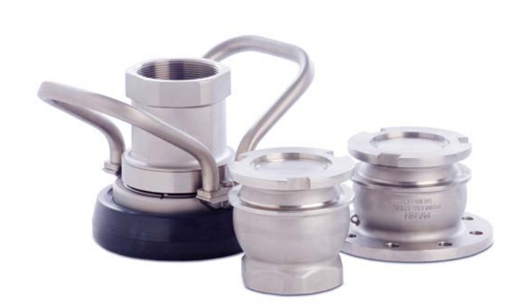
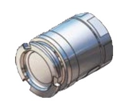
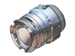
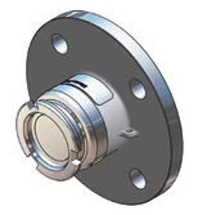
Tank Unit (Adapter) and Hose Unit (Coupler)
|
Material |
Maximum Working Pressure |
Test Pressure |
Minimum Burst Pressure |
|
Aluminium |
16 bar / 232 psi |
24 bar / 348 psi |
80 bar / 1160 psi |
|
Brass / Gunmetal |
16 bar / 232 psi |
24 bar / 348 psi |
80 bar / 1160 psi |
|
Stainless Steel |
25 bar / 363 psi |
37,5 bar / 544 psi |
125 bar / 1813 psi |
|
Titan |
25 bar / 363 psi |
37,5 bar / 544 psi |
125 bar / 1813 psi |
|
Hastelloy |
25 bar / 363 psi |
37,5 bar / 544 psi |
125 bar / 1813 psi |
|
PEEK |
6 bar / 87 psi |
9 bar / 131 psi |
30 bar / 435 psi |
¾", 1" and 1¼" in BSP, NPT or metrical thread, or flanged inlet.
For industrial process plant, road and rail tankers, IBC containers, pharmaceutical and petrochemical industries, diesel locomotive refuelling etc. Recommended for all types of mini bulk liquid product transfer, including container and drum filling, or on any application where spillage needs to be minimized.
Petroleum products: gasoline, diesel, oil etc.
Chemical products: e. g. ethylene oxide, propylene oxide, acrylonitrile, butadiene, ammonia, vinyl chloride, toluene, xylene, sulphuric acid, phenol etc.
Gas: vapor recovery/balance systems for various media.
Aluminium, brass, stainless steel, Hastelloy and PEEK. Others on request.
Standard seals in FPM (Viton®) - alternatively EPDM, FKM (Chemraz®, Kalrez®), NBR/HBNR. Other materials on request.
Allows maximum product transfer with minimal losses.
200 litres / minute (fuel).
To avoid product contamination caused by connecting a hose unit to the wrong tank unit, selective versions of the hose and tank units are available. Each unit has a number of selective positions, designated by a coded part number according to the coupling size, specify when placing order. See page 32 ff.
Compatible with couplings of other manufacturers.
All hose units are supplied with an integrated swivel.
|
Connection 1) Inch/DN |
Body Material 2) |
Seal |
Weight ≈ |
Mann Tek Code No. |
||
|
O-Ring 3) |
Flat Seal |
kg |
lbs |
|||
|
F ½" BSP |
Al |
Standard: FPM/FKM (Viton®)
Other on request. |
PUR (Polyurethane) |
0,3 |
0.7 |
T1133A1101B |
|
F ¾" BSP |
T101A1101B |
|||||
|
F 1" BSP |
T103A1101B |
|||||
|
F 1¼" BSP |
T105A1101B |
|||||
|
F M 54 x 1,5 |
T1138A1101B |
|||||
|
F ½" NPT |
— |
T1132A1101 |
||||
|
F ¾" NPT |
T102A1101 |
|||||
|
F 1" NPT |
T104A1101 |
|||||
|
F 1¼" NPT |
T106A1101 |
|||||
|
F ½" BSP |
Br |
PUR (Polyurethane) |
0,7 |
1.5 |
T1133A2201B |
|
|
F ¾" BSP |
T101A2201B |
|||||
|
F 1" BSP |
T103A2201B |
|||||
|
F 1¼" BSP |
T105A2201B |
|||||
|
F M 54 x 1,5 |
T1138A2201B |
|||||
|
F ½" NPT |
— |
T1132A2201 |
||||
|
F ¾" NPT |
T102A2201 |
|||||
|
F 1" NPT |
T104A2201 |
|||||
|
F 1¼" NPT |
T106A2201 |
|||||
|
F ½" BSP |
SS |
PTFE (Teflon®) |
0,7 |
1.5 |
T1133A4401B |
|
|
F ¾" BSP |
T101A4401A |
|||||
|
F 1" BSP |
T103A4401A |
|||||
|
F 1¼" BSP |
T105A4401A |
|||||
|
F M 54 x 1,5 |
T1138A4401A |
|||||
|
F ½" NPT |
— |
T1132A4401 |
||||
|
F ¾" NPT |
T102A4401 |
|||||
|
F 1" NPT |
T104A4401 |
|||||
|
F 1¼" NPT |
T106A4401 |
|||||
|
F ¾" BSP |
Titan |
PTFE (Teflon®) |
0,4 |
0.9 |
T101A6601A |
|
|
F 1" BSP |
T103A6601A |
|||||
|
F 1¼" BSP |
T105A6601A |
|||||
|
F ¾" NPT |
— |
T102A6601 |
||||
|
F 1" NPT |
T104A6601 |
|||||
|
F 1¼" NPT |
T106A6601 |
|||||
|
F ¾" BSP |
Hastelloy |
PTFE (Teflon®) |
0,8 |
1.8 |
T101A7701A |
|
|
F 1" BSP |
T103A7701A |
|||||
|
F 1¼" BSP |
T105A7701A |
|||||
|
F ¾" NPT |
— |
T102A7701 |
||||
|
F 1" NPT |
T104A7701 |
|||||
|
F 1¼" NPT |
T106A7701 |
|||||
|
F ¾" BSP |
PEEK |
PTFE (Teflon®) |
0,1 |
0.2 |
T101A9901A |
|
|
F 1" BSP |
T103A9901A |
|||||
|
F 1¼" BSP |
T105A9901A |
|||||
|
F ¾" NPT |
— |
T102A9901 |
||||
|
F 1" NPT |
T104A9901 |
|||||
|
F 1¼" NPT |
T106A9901 |
|||||
1) F = Female thread, BSP = EN ISO 228, NPT = ANSI B1.20.1
2) Material: Al = Aluminium, Br = Brass, SS = Stainless Steel
3) Standard seal FPM/FKM. Alternative materials, e. g. EPDM, Chemraz®, Kalrez®, NBR or HNBR on request.
Viton® and Teflon® are registred trademarks of DuPont, DuPont Elastomers.
|
Connection 1) Inch/DN |
Body Material 2) |
Seal 3) |
Weight ≈ |
Mann Tek Code No. |
||
|
O-Ring |
kg |
lbs |
||||
|
M ¾" BSP |
|
|
|
|
T169A1101 |
|
|
M ¾" NPT |
Al |
|
T170A1101 |
|||
|
M 1" BSP |
T171A1101 |
|||||
|
M 1" NPT |
|
Standard: |
T172A1101 |
|||
|
M ¾" BSP |
|
|
|
T169A1101 |
||
|
|
FPM/FKM |
|||||
|
M ¾" NPT |
T170A1101 |
|||||
|
Br |
(Viton®)
Other on |
|||||
|
M 1" BSP |
T171A1101 |
|||||
|
M 1" NPT |
T172A1101 |
|||||
|
|
request. |
|||||
|
M ¾" BSP |
|
|
|
T169A4401 |
||
|
M ¾" NPT |
SS |
|
T170A4401 |
|||
|
M 1" BSP |
T171A4401 |
|||||
|
M 1" NPT |
|
|
T172A4401 |
|||
1) M = Male thread, BSP = EN ISO 228, NPT = ANSI B1.20.1
2) Material: Al = Aluminium, Br = Brass, SS = Stainless Steel,
3) Standard seal FPM/FKM. Alternative materials, e. g. EPDM, Chemraz®, Kalrez®, NBR or HNBR on request.
|
Flange 1) |
Body Material 2) |
Seal 3) |
Weight ≈ |
Mann Tek Code No. |
||
|
O-Ring |
kg |
lbs |
||||
|
undrilled |
|
|
|
|
T118A1101 |
|
|
DN 25 PN 10 / 16 Type A |
|
|
|
|
T123A1101 |
|
|
DN 25 PN 25 / 40 Type A |
Al |
|
1,1 |
2.4 |
T124A1101 |
|
|
1" ASA 150 |
|
|
|
|
T151A1101 |
|
|
1" ASA 300 |
|
|
|
|
T152A1101 |
|
|
undrilled |
|
|
|
T118A2201 |
||
|
DN 25 PN 10 / 16 Type B |
|
|
|
|
T123A2201 |
|
|
DN 25 PN 25 / 40 Type B |
Br |
|
1,6 |
3.5 |
T124A2201 |
|
|
1" ASA 150 |
|
|
|
|
T151A2201 |
|
|
1" ASA 300 |
|
|
|
|
T152A2201 |
|
|
undrilled |
|
1,5 |
3.3 |
T118A4401 |
||
|
DN 25 PN 10 / 16 Type B |
|
|
T123A4401 |
|||
|
DN 25 PN 25 / 40 Type B |
SS |
Standard: |
T124A4401 |
|||
|
|
FPM/FKM |
|||||
|
1" ASA 150 |
T151A4401 |
|||||
|
|
(Viton®) |
|||||
|
1" ASA 300 |
T152A4401 |
|||||
|
undrilled |
|
Other on |
|
|
T118A6601 |
|
|
DN 25 PN 10 / 16 Type B |
T123A6601 |
|||||
|
|
request. |
|
|
|||
|
DN 25 PN 25 / 40 Type B |
Titan |
|
0,8 |
1.8 |
T124A6601 |
|
|
1" ASA 150 |
|
|
|
|
T151A6601 |
|
|
1" ASA 300 |
|
|
|
|
T152A6601 |
|
|
DN 25 PN 10 / 16 Type B |
|
|
|
T123A7701 |
||
|
DN 25 PN 25 / 40 Type B |
Hastelloy |
|
1,7 |
3.8 |
T124A7701 |
|
|
1" ASA 150 |
T151A7701 |
|||||
|
1" ASA 300 |
|
|
|
|
T152A7701 |
|
|
undrilled |
|
|
|
T118A9901 |
||
|
DN 25 PN 10 / 16 Type B |
|
|
|
|
T123A9901 |
|
|
DN 25 PN 25 / 40 Type B |
PEEK |
|
0,2 |
0.4 |
T124A9901 |
|
|
1" ASA 150 |
|
|
|
|
T151A9901 |
|
|
1" ASA 300 |
|
|
|
|
T152A9901 |
|
1) PN 10 / 16 / 25 / 40 = EN 1092 (types see page 44), ANSI B16.5.
2) Material: Al = Aluminium, Br = Brass, SS = Stainless Steel
3) Standard seal FPM/FKM. Alternative materials, e. g. EPDM, Chemraz®, Kalrez®, NBR or HNBR on request.
Viton® is a registred trademark of DuPont, DuPont Elastomers.
|
Connection 1) Inch/DN |
Body Material 2) |
Seal |
Weight ≈ |
Mann Tek Code No. |
||
|
O-Ring 3) |
Thread Seal |
kg |
lbs |
|||
|
F ½" BSP |
Al |
Standard: FPM/FKM (Viton®)
Other on request. |
PUR (Polyurethane) |
0,5 |
1.1 |
S1133A1101B |
|
F ¾" BSP |
S101A1101B |
|||||
|
F 1" BSP |
S103A1101B |
|||||
|
F 1¼" BSP |
S105A1101B |
|||||
|
F M 54 x 1,5 |
S1138A1101B |
|||||
|
F ½" NPT |
— |
S1132A1101 |
||||
|
F ¾" NPT |
S102A1101 |
|||||
|
F 1" NPT |
S104A1101 |
|||||
|
F 1¼" NPT |
S106A1101 |
|||||
|
F ½" BSP |
Br |
PUR (Polyurethane) |
1,4 |
3.1 |
S1133A2201B |
|
|
F ¾" BSP |
S101A2201B |
|||||
|
F 1" BSP |
S103A2201B |
|||||
|
F 1¼" BSP |
S105A2201B |
|||||
|
F M 54 x 1,5 |
S1138A2201B |
|||||
|
F ½" NPT |
— |
S1132A2201 |
||||
|
F ¾" NPT |
S102A2201 |
|||||
|
F 1" NPT |
S104A2201 |
|||||
|
F 1¼" NPT |
S106A2201 |
|||||
|
F ½" BSP |
SS |
PTFE (Teflon®) |
1,3 |
2.9 |
S1133A4401A |
|
|
F ¾" BSP |
S101A4401A |
|||||
|
F 1" BSP |
S103A4401A |
|||||
|
F 1¼" BSP |
S105A4401A |
|||||
|
F M 54 x 1,5 |
S1138A4401A |
|||||
|
F ½" NPT |
— |
S1132A4401 |
||||
|
F ¾" NPT |
S102A4401 |
|||||
|
F 1" NPT |
S104A4401 |
|||||
|
F 1¼" NPT |
S106A4401 |
|||||
|
F ¾" BSP |
Titan |
PTFE (Teflon®) |
0,7 |
1.5 |
S101A6601A |
|
|
F 1" BSP |
S103A6601A |
|||||
|
F 1¼" BSP |
S105A6601A |
|||||
|
F ¾" NPT |
— |
S102A6601 |
||||
|
F 1" NPT |
S104A6601 |
|||||
|
F 1¼" NPT |
S106A6601 |
|||||
|
F ¾" BSP |
Hastelloy |
PTFE (Teflon®) |
1,5 |
3.3 |
S101A7701A |
|
|
F 1" BSP |
S103A7701A |
|||||
|
F 1¼" BSP |
S105A7701A |
|||||
|
F ¾" NPT |
— |
S102A7701 |
||||
|
F 1" NPT |
S104A7701 |
|||||
|
F 1¼" NPT |
S106A7701 |
|||||
|
F ¾" BSP |
PEEK |
PTFE (Teflon®) |
0,3 |
0.7 |
S101A9901A |
|
|
F 1" BSP |
S103A9901A |
|||||
|
F 1¼" BSP |
S105A9901A |
|||||
|
F ¾" NPT |
— |
S102A9901 |
||||
|
F 1" NPT |
S104A9901 |
|||||
|
F 1¼" NPT |
S106A9901 |
|||||
1) F = Female thread, BSP = EN ISO 228, NPT = ANSI B1.20.1
2) Material: Al = Aluminium, Br = Brass, SS = Stainless Steel
3) Standard seal FPM/FKM. Alternative materials, e. g. EPDM, Chemraz®, Kalrez®, NBR or HNBR on request.
Viton® and Teflon® are registred trademarks of DuPont, DuPont Elastomers.
|
Connection 1) Inch/DN |
Body Material 2) |
Seal 3) |
Weight ≈ |
Mann Tek Code No. |
||
|
O-Ring |
kg |
lbs |
||||
|
M ¾" BSP |
|
|
|
|
S169A1101 |
|
|
M ¾" NPT |
Al |
|
S170A1101 |
|||
|
M 1" BSP |
S171A1101 |
|||||
|
M 1" NPT |
|
Standard: |
S172A1101 |
|||
|
M ¾" BSP |
|
|
|
S169A1101 |
||
|
|
FPM/FKM |
|||||
|
M ¾" NPT |
S170A1101 |
|||||
|
Br |
(Viton®)
Other on |
|||||
|
M 1" BSP |
S171A1101 |
|||||
|
M 1" NPT |
S172A1101 |
|||||
|
|
request. |
|||||
|
M ¾" BSP |
|
|
|
S169A4401 |
||
|
M ¾" NPT |
SS |
|
|
|
S170A4401 |
|
|
M 1" BSP |
|
|
S171A4401 |
|||
|
M 1" NPT |
|
|
1,4 |
3.0 |
S172A4401 |
|
1) M = Male thread, BSP = EN ISO 228, NPT = ANSI B1.20.1
2) Material: Al = Aluminium, Br = Brass, SS = Stainless Steel
3) Standard seal FPM/FKM. Alternative materials,
e. g. EPDM, Chemraz®, Kalrez®, NBR or HNBR on request.
|
Flange 1) |
Body Material 2) |
Seal 3) |
Weight ≈ |
Mann Tek Code No. |
|
|
O-Ring |
kg |
lbs |
|||
|
undrilled |
Al |
Standard: FPM/FKM (Viton®)
Other on request. |
1,1 |
2.4 |
S118A1101 |
|
DN 25 PN 10 / 16 Type A |
S123A1101 |
||||
|
DN 25 PN 25 / 40 Type A |
S124A1101 |
||||
|
¾" ASA 150 |
S149A1101 |
||||
|
1" ASA 150 |
S151A1101 |
||||
|
1" ASA 300 |
S152A1101 |
||||
|
DN 25 DIN 11864 |
S1151A1101 |
||||
|
undrilled |
Br |
1,6 |
3.5 |
S118A2201 |
|
|
DN 25 PN 10 / 16 Type B |
S123A2201 |
||||
|
DN 25 PN 25 / 40 Type B |
S124A2201 |
||||
|
¾" ASA 150 |
S149A2201 |
||||
|
1" ASA 150 |
S151A2201 |
||||
|
1" ASA 300 |
S152A2201 |
||||
|
undrilled |
SS |
2,2 |
4.9 |
S118A4401 |
|
|
DN 25 PN 10 / 16 Type B |
S123A4401 |
||||
|
DN 25 PN 25 / 40 Type B |
S124A4401 |
||||
|
¾" ASA 150 |
S149A4401 |
||||
|
1" ASA 150 |
S151A4401 |
||||
|
1" ASA 300 |
S152A4401 |
||||
|
undrilled |
Titan |
1,2 |
2.7 |
S118A6601 |
|
|
DN 25 PN 10 / 16 Type B |
S123A6601 |
||||
|
DN 25 PN 25 / 40 Type B |
S124A6601 |
||||
|
1" ASA 150 |
S151A6601 |
||||
|
1" ASA 300 |
S152A6601 |
||||
|
DN 25 PN 10 / 16 Type B |
Hastelloy |
2,5 |
5.5 |
S123A7701 |
|
|
DN 25 PN 25 / 40 Type B |
S124A7701 |
||||
|
1" ASA 150 |
S151A7701 |
||||
|
1" ASA 300 |
S152A7701 |
||||
|
undrilled |
PEEK |
0,5 |
1.1 |
S118A9901 |
|
|
DN 25 PN 10 / 16 Type B |
S123A9901 |
||||
|
DN 25 PN 25 / 40 Type B |
S124A9901 |
||||
|
1" ASA 150 |
S151A9901 |
||||
|
1" ASA 300 |
S152A9901 |
||||
1) PN 10 / 16 / 25 / 40 = EN 1092
ASA = ANSI B16.5 (150 o. 300 psi), 150
or 300 psi.
DIN 11864 = DIN 11864-2 (aseptic flange)
2) Material: Al = Aluminium,
Br = Brass, SS = Stainless Steel
3) Standard seal FPM/FKM. Alternative materials, e. g. EPDM, Chemraz®, Kalrez®, NBR or HNBR on request.
Viton® is a registred trademark of DuPont, DuPont Elastomers.
Tank Unit (Adapter) and Hose Unit (Coupler)
|
Material |
Maximum Working Pressure |
Test Pressure |
Minimum Burst Pressure |
|
Aluminium |
16 bar / 232 psi |
24 bar / 348 psi |
80 bar / 1160 psi |
|
Brass / Gunmetal |
16 bar / 232 psi |
24 bar / 348 psi |
80 bar / 1160 psi |
|
Stainless Steel |
25 bar / 363 psi |
37,5 bar / 544 psi |
125 bar / 1813 psi |
|
Titan |
25 bar / 363 psi |
37,5 bar / 544 psi |
125 bar / 1813 psi |
|
Hastelloy |
25 bar / 363 psi |
37,5 bar / 544 psi |
125 bar / 1813 psi |
|
PEEK |
6 bar / 87 psi |
9 bar / 131 psi |
30 bar / 435 psi |
1½" and 2" in BSP, NPT or S60x6 thread, or flanged inlet.
For industrial process plant, road and rail tankers, ISO tank containers, IBC containers, pharmaceutical and petrochemical industries or on any application where spillage needs to be minimized.
Petroleum products: gasoline, diesel, oil etc. Chemical products: AdBlue, ethylene oxide, propylene oxide, acrylonitrile, butadiene, ammonia, vinyl chloride, toluene, xylene, sulphuric acid, phenol etc.
Gas: vapor recovery/balance systems for for various media.
Dry powder.
Aluminium, brass/gunmetal, stainless steel, Hastelloy and PEEK. Other materials on request.
Standard seals in FPM (Viton®) - alternatively EPDM, FKM (Chemraz®, Kalrez®), NBR/HBNR. Other materials on request.
Allows maximum product transfer with minimal losses.
900 litres/minute (fuel)
To avoid product contamination caused by connecting a hose unit to the wrong tank unit, selective versions of the hose and tank units are available. Each unit has a number of selective positions, desig- nated by a coded part number according to the coup- ling size – specify when placing order. See page 32 ff.
Compatible with couplings of other manufacturers.
All hose units are supplied with an integrated swivel.
According to NATO STANAG 3756
|
Connection 1) Inch/DN |
Body Material 2) |
Seal |
Weight ≈ |
Mann Tek Code No. |
||
|
O-Ring 3) |
Thread Seal |
kg |
lbs |
|||
|
F 1½" BSP |
Al |
Standard: FPM/FKM (Viton®)
Other on request. |
PUR (Polyurethane) |
0,4 |
0.8 |
T207A1101B |
|
F 2" BSP |
T210A1101B |
|||||
|
F S60x6 |
T2108A1101B |
|||||
|
F W2" - 7 |
T2112A1101B |
|||||
|
F 1½" NPT |
— |
0.4 |
0.8 |
T208A1101 |
||
|
F 2" NPT |
T211A1101 |
|||||
|
F 1½" BSP |
Br |
PUR (Polyurethane) |
1,2 |
2.7 |
T207A2201B |
|
|
F 2" BSP |
1,1 |
2.4 |
T210A2201B |
|||
|
F S 60 x 6 |
1,0 |
2.2 |
T2108A2201B |
|||
|
F W2" - 7 |
1,0 |
0.9 |
T2112A2201B |
|||
|
F 1½" NPT |
— |
0,4 |
0.9 |
T208A2201 |
||
|
F 2" NPT |
1,1 |
2.4 |
T211A2201 |
|||
|
F 1½" BSP |
SS |
PTFE (Teflon®) |
1,1 |
2.4 |
T207A4401A |
|
|
F 2" BSP |
1,0 |
2.2 |
T210A4401A |
|||
|
F S60 x 6 |
1,0 |
2.2 |
T2108A4401A |
|||
|
F 1½" NPT |
— |
1,2 |
2.7 |
T208A4401 |
||
|
F 2" NPT |
1,1 |
2.4 |
T211A4401 |
|||
|
F 1½" BSP |
Titan |
PTFE (Teflon®) |
|
|
T207A6601A |
|
|
F 2" BSP |
0,6 |
1.3 |
T210A6601A |
|||
|
F 1½" NPT |
— |
|
|
T208A6601 |
||
|
F 2" NPT |
0,6 |
1.3 |
T211A6601 |
|||
|
F 1½" BSP |
Hastelloy |
PTFE (Teflon®) |
|
|
T207A7701A |
|
|
F 2" BSP |
|
|
T210A7701A |
|||
|
F 1½" NPT |
— |
|
|
T208A7701 |
||
|
F 2" NPT |
|
|
T211A7701 |
|||
|
F 1½" BSP |
PEEK |
PTFE (Teflon®) |
|
|
T207A9901A |
|
|
F 2" BSP |
0,3 |
0.6 |
T210A9901A |
|||
|
F 1½" NPT |
— |
|
|
T208A9901 |
||
|
F 2" NPT |
0,3 |
0.6 |
T211A9901 |
|||
1) F = Female thread, BSP = EN ISO 228, NPT = ANSI B1.20.1, S60 x 6 = thread for IBC, W 2" heating oil connection Sweden
2) Material: Al = Aluminium, Br = Brass, SS = Stainless Steel
3) Standard seal FPM/FKM. Alternative materials, e. g. EPDM, Chemraz®, Kalrez®, NBR or HNBR on request.
According to NATO STANAG 3756
|
Flange 1) |
Body Material 2) |
Seal 3) |
Weight ≈ |
Mann Tek Code No. |
||
|
O-Ring |
kg |
lbs |
||||
|
M 2" BSP |
|
|
1,0 |
2.2 |
T278A1101 |
|
|
M 2" NPT |
Al |
Standard: |
|
|
T279A1101 |
|
|
M W2" - 7 |
|
|
T2123A1101 |
|||
|
|
FPM/FKM |
|||||
|
M 2" BSP |
|
|
|
T278A2201 |
||
|
Br |
(Viton®) |
|||||
|
M 2" NPT |
|
|
T279A2201 |
|||
|
M W2" - 7 |
|
Other on |
|
|
T2123A2201 |
|
|
|
request. |
|||||
|
M 2" BSP |
SS |
1,0 |
2.2 |
T278A4401 |
||
|
M 2" NPT |
|
1,1 |
2.4 |
T279A4401 |
||
1) M = Male thread, BSP = EN ISO 228, NPT = ANSI B1.20.1, S 60 x 6 = thread for IBC, W 2" heating oil connection Sweden
2) Material: Al = Aluminium, Br = Brass, SS = Stainless Steel
3) Standard seal FPM/FKM. Alternative materials, e. g. EPDM, Chemraz®, Kalrez®, NBR or HNBR on request.
Viton® is a registred trademark of DuPont, DuPont Elastomers.
According to NATO STANAG 3756
|
Flange 1) |
Body Material 2) |
Seal 3) |
Weight ≈ |
Mann Tek Code No. |
|
|
O-Ring |
kg |
lbs |
|||
|
undrilled Ø 165 mm |
Al |
Standard: FPM/FKM (Viton®)
Other on request. |
1,0 |
2.2 |
T219B1101 |
|
DN 40 PN 10 / 16 Type A |
0,9 |
2.0 |
T227B1101 |
||
|
1½" ASA 150 |
0,8 |
1.8 |
T255B1101 |
||
|
DN 50 PN 10 / 16 Type A |
1,0 |
2.2 |
T230B1101 |
||
|
2" ASA 150 |
0,9 |
2.0 |
T257B1101 |
||
|
DIN 28459 'TW 1' / DN 80 |
0,9 |
2.0 |
T265B1101 |
||
|
undrilled Ø 165 mm |
GM |
3,3 |
7.3 |
T219B2201 |
|
|
DN 40 PN 10 / 16 Type B |
2,5 |
5.5 |
T227B2201 |
||
|
DN 40 PN 25 / 40 Type B |
|
|
T228B2201 |
||
|
1½" ASA 150 |
2,2 |
4.9 |
T255B2201 |
||
|
1½" ASA 300 |
|
|
T256B2201 |
||
|
DN 50 PN 10 / 16 Type B |
3,1 |
6.8 |
T230B2201 |
||
|
DN 50 PN 25 / 40 Type B |
|
|
T231B2201 |
||
|
2" ASA 150 |
2,5 |
5.1 |
T257B2201 |
||
|
2" ASA 300 |
|
|
T258B2201 |
||
|
DIN 28459 'TW 1' / DN 80 |
2,4 |
5.3 |
T265B2201 |
||
|
undrilled Ø 165 mm |
SS |
3,2 |
7.1 |
T219B4401 |
|
|
undrilled Ø 165 mm **) |
|
|
T219B4401F |
||
|
DN 40 PN 10 / 16 Type B |
2,4 |
5.3 |
T227B4401 |
||
|
DN 40 PN 10 / 16 Type B **) |
|
|
T227B4401F |
||
|
DN 40 PN 25 / 40 Type B |
2,4 |
5.3 |
T228B4401 |
||
|
DN 40 PN 25 / 40 Type B **) |
|
|
T228B4401F |
||
|
1½" ASA 150 |
1,7 |
3.8 |
T255B4401 |
||
|
1½" ASA 150 **) |
|
|
T255B4401F |
||
|
1½" ASA 300 |
2,1 |
4.6 |
T256B4401 |
||
|
1½" ASA 300 **) |
|
|
T256B4401F |
||
|
DN 50 PN 25 / 40 Type E *) |
2,9 |
6.4 |
T229B4401 |
||
|
DN 50 PN 10 / 16 Type B ) |
2,7 |
6.0 |
T230B4401 |
||
|
DN 50 PN 10 / 16 Type B ** |
|
|
T230B4401F |
||
|
DN 50 PN 25 / 40 Type B |
3,0 |
6.6 |
T231B4401 |
||
|
DN 50 PN 25 / 40 Type B **) |
|
|
T231B4401F |
||
|
2" ASA 150 |
2,4 |
5.3 |
T257B4401 |
||
|
2" ASA 150 **) |
|
|
T257B4401F |
||
|
2" ASA 300 |
2,5 |
5.5 |
T258B4401 |
||
|
2" ASA 300 **) |
|
|
T258B4401F |
||
|
DIN 28459 'TW 1' / DN 80 |
|
|
T265B4401 |
||
|
DN 50 DIN 11864 |
|
|
T2152B4401 |
||
|
undrilled Ø 165 mm |
Titan |
|
|
T219A6601 |
|
|
DN 40 PN 10 / 16 Type B |
|
|
T227A6601 |
||
|
DN 40 PN 25 / 40 Type B |
|
|
T228A6601 |
||
|
1½" ASA 150 |
1,7 |
3.8 |
T255A6601 |
||
|
1½" ASA 300 |
|
|
T256A6601 |
||
|
DN 50 PN 10 / 16 Type B |
|
|
T230A6601 |
||
|
DN 50 PN 25 / 40 Type B |
|
|
T231A6601 |
||
|
2" ASA 150 |
|
|
T257A6601 |
||
|
2" ASA 300 |
|
|
T258A6601 |
||
|
undrilled Ø 165 mm |
Hastelloy |
|
|
T219A7701 |
|
|
DN 40 PN 10 / 16 Type B |
|
|
T227A7701 |
||
|
DN 40 PN 25 / 40 Type B |
|
|
T228A7701 |
||
|
1½" ASA 150 |
|
|
T255A7701 |
||
|
1½" ASA 300 B |
|
|
T256A7701 |
||
|
DN 50 PN 10 / 16 Type B |
|
|
T230A7701 |
||
|
DN 50 PN 25 / 40 Type B |
|
|
T231A7701 |
||
|
2" ASA 150 |
|
|
T257A7701 |
||
|
2" ASA 300 |
|
|
T258A7701 |
||
|
undrilled Ø 165 mm |
PEEK |
|
|
T219A9901 |
|
|
DN 40 PN 10 / 16 Type B |
1,0 |
2.0 |
T227A9901 |
||
|
1½" ASA 150 |
|
|
T255A9901 |
||
|
DN 50 PN 10 / 16 Type B |
1,0 |
2.0 |
T230A9901 |
||
|
2" ASA 150 |
1,0 |
2.0 |
T257A9901 |
||
*) Type E (with spigot), EN 1092-1, see p. 44
**) Flange with standard thickness
1) PN 10 / 16 / 25 / 40 = EN 1092
(types see page 44),
ASA = ANSI B16.5 (150 o. 300 psi),
DIN 28459 = old standard TW, 10 bar. DIN 11864 = DIN 11864-2 (aseptic flange)
2) Material: Al = Aluminium,
GM = Gunmetal, SS = Stainless Steel
3) Standard seal FPM/FKM. Alternative materials, e. g. EPDM, Chemraz®, Kalrez®, NBR or HNBR on request.
Viton® is a registred trademark of DuPont, DuPont Elastomers.
According to NATO STANAG 3756
|
Connection 1) Inch/DN |
Body Material 2) |
Seal |
Weight ≈ |
Mann Tek Code No. |
||
|
O-Ring 3) |
Thread Seal |
kg |
lbs |
|||
|
F 1½" BSP |
Al |
Standard: FPM/FKM (Viton®)
Other on request. |
PUR (Polyurethane) |
1,2 |
2.7 |
S207A1101B |
|
F 1½" BSP-B Mouth*) |
|
|
S207A1101BI |
|||
|
F 2" BSP |
1,1 |
2.4 |
S210A1101B |
|||
|
F 2" BSP-B Mouth*) |
1,1 |
2.4 |
S210A1101BI |
|||
|
F 1½" NPT |
— |
1,1 |
2.4 |
S208A1101 |
||
|
F 1½" NPT-B Mouth*) |
|
|
S208A1101I |
|||
|
F 2" NPT |
1,1 |
2.4 |
S211A1101 |
|||
|
F 2" NPT-B Mouth*) |
|
|
S211A1101I |
|||
|
F 1½" BSP |
Br |
PUR (Polyurethane) |
2,6 |
5.7 |
S207A2201B |
|
|
F 1½" BSP-B Mouth*) |
|
|
S207A2201BI |
|||
|
F 2" BSP |
2,4 |
5.3 |
S210A2201B |
|||
|
F 2" BSP-B Mouth*) |
|
|
S210A2201BI |
|||
|
F 1½" NPT |
— |
2,5 |
5.5 |
S208A2201 |
||
|
F 1½" NPT-B Mouth*) |
|
|
S208A2201I |
|||
|
F 2" NPT |
2,5 |
5.5 |
S211A2201 |
|||
|
F 2" NPT-B Mouth*) |
|
|
S211A2201I |
|||
|
F 1½" BSP |
SS |
PTFE (Teflon®) |
2,5 |
5.5 |
S207A4401A |
|
|
F 2" BSP |
2,3 |
5.1 |
S210A4401A |
|||
|
F 1½" NPT |
— |
2,4 |
5.3 |
S208A4401 |
||
|
F 2" NPT |
2,3 |
5.1 |
S211A4401 |
|||
|
F 1½" BSP |
Titan |
PTFE (Teflon®) |
1,3 |
2.9 |
S207A6601A |
|
|
F 2" BSP |
1,3 |
2.9 |
S210A6601A |
|||
|
F 1½" NPT |
— |
|
|
S208A6601 |
||
|
F 2" NPT |
1,4 |
3.1 |
S211A6601 |
|||
|
F 1½" BSP |
Hastelloy |
PTFE (Teflon®) |
2,3 |
5.1 |
S207A7701A |
|
|
F 2" BSP |
2,3 |
5.1 |
S210A7701A |
|||
|
F 1½" NPT |
— |
2,3 |
5.1 |
S208A7701 |
||
|
F 2" NPT |
2,3 |
5.1 |
S211A7701 |
|||
|
F 1½" BSP |
PEEK |
PTFE (Teflon®) |
|
|
S207A9901A |
|
|
F 2" BSP |
1,3 |
2.9 |
S210A9901A |
|||
|
F 1½" NPT |
— |
|
|
S208A9901 |
||
|
F 2" NPT |
1,3 |
2.9 |
S211A9901 |
|||
*) Adopted for older models of Emco Wheaton male couplings
1) F = Female thread, BSP =
EN ISO 228, NPT = ANSI B1.20.1
2) Material: Al = Aluminium, Br = Brass, SS = Stainless Steel
3) Standard seal FPM/FKM. Alternative materials, e. g. EPDM, Chemraz®, Kalrez®, NBR or HNBR on request.
According to NATO STANAG 3756
|
Flange 1) |
Body Material 2) |
Seal 3) |
Weight ≈ |
Mann Tek Code No. |
|
|
O-Ring |
kg |
lbs |
|||
|
2" BSP AG |
Al |
Standard: FPM/FKM (Viton®)
Other on request. |
|
|
S278A1101 |
|
2" NPT AG |
|
|
S279A1101 |
||
|
S60 x 6 AG |
|
|
S2109A1101 |
||
|
W2" - 7 AG |
1,3 |
2.1 |
S2123A1101 |
||
|
2" BSP AG |
Br |
|
|
S278A2201 |
|
|
2" NPT AG |
|
|
S279A2201 |
||
|
S60x6 AG |
|
|
S2109A2201 |
||
|
W2" - 7 AG |
|
|
S2123A2201 |
||
|
2" BSP AG |
SS |
2,3 |
5.1 |
S278A4401 |
|
|
2" NPT AG |
|
|
S279A4401 |
||
|
S60x6 AG |
|
|
S2109A4401 |
||
1) M = Male thread, BSP = EN ISO 228, NPT = ANSI B1.20.1, S 60 x 6 = thread for IBC, W 2" heating oil connection Sweden
2) Material: Al = Aluminium, Br = Brass, SS = Stainless Steel
3) Standard seal FPM/FKM. Alternative materials, e. g. EPDM, Chemraz®, Kalrez®, NBR or HNBR on request.
Viton® and Teflon® are registred trademarks of DuPont, DuPont Elastomers.
According to NATO STANAG 3756
|
Flange 1) |
Body Material 2) |
Seal 3) |
Weight ≈ |
Mann Tek Code No. |
|
|
O-Ring |
kg |
lbs |
|||
|
undrilled Ø 165 mm |
Al |
Standard: FPM/FKM (Viton®)
Other on request. |
|
|
S219A1101 |
|
DN 40 PN 10 / 16 Type A |
|
|
S227A1101 |
||
|
1½" ASA 150 |
|
|
S255A1101 |
||
|
DN 50 PN 10 / 16 Type A |
2,3 |
5.1 |
S230A1101 |
||
|
2" ASA 150 |
|
|
S257A1101 |
||
|
DIN 28459 'TW 1' / DN 80 |
|
|
S265A1101 |
||
|
undrilled Ø 165 mm |
GM |
|
|
S219A2201 |
|
|
DN 40 PN 10 / 16 Type B |
|
|
S227A2201 |
||
|
DN 40 PN 25 / 40 Type B |
|
|
S228A2201 |
||
|
1½" ASA 150 |
5,1 |
11.2 |
S255A2201 |
||
|
1½" ASA 300 |
|
|
S256A2201 |
||
|
DN 50 PN 10 / 16 Type B |
|
|
S230A2201 |
||
|
DN 50 PN 25 / 40 Type B |
|
|
S231A2201 |
||
|
2" ASA 150 |
5,1 |
11.2 |
S257A2201 |
||
|
2" ASA 300 |
|
|
S258A2201 |
||
|
DIN 28459 'TW 1' / DN 80 |
|
|
S265A2201 |
||
|
undrilled Ø 165 mm |
SS |
|
|
S219A4401 |
|
|
o. Bohrungen Ø 165 mm **) |
|
|
S219A4401F |
||
|
DN 40 PN 10 / 16 Type B |
|
|
S227A4401 |
||
|
DN 40 PN 10 / 16 Type B **) |
|
|
S227A4401F |
||
|
DN 40 PN 25 / 40 Type B |
|
|
S228A4401 |
||
|
DN 40 PN 25 / 40 Type B **) |
|
|
S228A4401F |
||
|
1½" ASA 150 |
|
|
S255A4401 |
||
|
1½" ASA 150 **) |
|
|
S255A4401F |
||
|
1½" ASA 300 |
|
|
S256A4401 |
||
|
1½" ASA 300 **) |
6,6 |
14.6 |
S256A4401F |
||
|
DN 50 PN 25 / 40 Type E *) |
|
|
S229A4401 |
||
|
DN 50 PN 10 / 16 Type B |
5,4 |
11.9 |
S230A4401 |
||
|
DN 50 PN 10 / 16 Type B **) |
|
|
S230A4401F |
||
|
DN 50 PN 25 / 40 Type B |
5,4 |
11.9 |
S231A4401 |
||
|
DN 50 PN 25 / 40 Type B **) |
|
|
S231A4401F |
||
|
2" ASA 150 |
5,1 |
11.2 |
S257A4401 |
||
|
2" ASA 150 **) |
5,1 |
11.2 |
S257A4401F |
||
|
2" ASA 300 |
|
|
S258A4401 |
||
|
2" ASA 300 **) |
2,5 |
5.5 |
S258A4401F |
||
|
DIN 28459 'TW 1' / DN 80 |
|
|
S265A4401 |
||
|
DN 50 DIN 11864 |
3,1 |
6.8 |
S2152B4401 |
||
|
undrilled Ø 165 mm |
Titan |
|
|
S219A6601 |
|
|
DN 40 PN 10 / 16 Type B |
|
|
S227A6601 |
||
|
DN 40 PN 25 / 40 Type B |
|
|
S228A6601 |
||
|
1½" ASA 150 |
|
|
S255A6601 |
||
|
1½" ASA 300 |
|
|
S256A6601 |
||
|
DN 50 PN 10 / 16 Type B |
|
|
S230A6601 |
||
|
DN 50 PN 25 / 40 Type B |
|
|
S231A6601 |
||
|
2" ASA 150 |
|
|
S257A6601 |
||
|
2" ASA 300 |
|
|
S258A6601 |
||
|
undrilled Ø 165 mm |
Hastelloy |
|
|
S219A7701 |
|
|
DN 40 PN 10 / 16 Type B |
|
|
S227A7701 |
||
|
DN 40 PN 25 / 40 Type B |
|
|
S228A7701 |
||
|
1½" ASA 150 |
|
|
S255A7701 |
||
|
1½" ASA 300 |
|
|
S256A7701 |
||
|
DN 50 PN 10 / 16 Type B |
5,4 |
11.9 |
S230A7701 |
||
|
DN 50 PN 25 / 40 Type B |
|
|
S231A7701 |
||
|
2" ASA 150 |
|
|
S257A7701 |
||
|
2" ASA 300 |
|
|
S258A7701 |
||
|
undrilled Ø 165 mm |
PEEK |
|
|
S219A9901 |
|
|
DN 40 PN 10 / 16 Type B |
5,4 |
11.9 |
S227A9901 |
||
|
1½" ASA 150 Type B |
|
|
S255A9901 |
||
|
DN 50 PN 10 / 16 Type B |
5,4 |
11.9 |
S230A9901 |
||
|
2" ASA 150 |
|
|
S257A9901 |
||
*) Type E (with spigot),
EN 1092-1, see page 44
**) Flange with standard thickness
1) PN 10 / 16 / 25 / 40 = EN 1092
(types see page 44),
ASA = ANSI B16.5 (150 o. 300 psi),
DIN 28459 = old standard TW, 10 bar. DIN 11864 = DIN 11864-2 (aseptic flange).
2) Material: Al = Aluminium,
GM = Gunmetal, SS = Stainless Steel
3) Standard seal FPM/FKM. Alternative materials, e. g. EPDM, Chemraz®, Kalrez®, NBR or HNBR on request.
Viton® is a registred trademark of DuPont, DuPont Elastomers.
Tank Unit (Adapter) and Hose Unit (Coupler)
|
Material |
Maximum Working Pressure |
Test Pressure |
Minimum Burst Pressure |
|
Aluminium |
10 bar / 145 psi |
15 bar / 218 psi |
50 bar / 726 psi |
|
Brass / Gunmetal |
16 bar / 232 psi |
24 bar / 348 psi |
80 bar / 1160 psi |
|
Stainless Steel |
25 bar / 363 psi |
37,5 bar / 544 psi |
125 bar / 1813 psi |
|
Titan |
25 bar / 363 psi |
37,5 bar / 544 psi |
125 bar / 1813 psi |
|
Hastelloy |
25 bar / 363 psi |
37,5 bar / 544 psi |
125 bar / 1813 psi |
|
PEEK |
6 bar / 87 psi |
9 bar / 131 psi |
30 bar / 435 psi |
2½" and 3" in BSP, NPT and flanged inlet.
For road and rail tanker bottom loading/unloading, tanks and containers, or on any application where product contamination and spillage needs to be minimized.
Petroleum products: gasoline, diesel, oil etc. Chemical products: ethylene oxide, propylene oxide, acrylonitrile, butadiene, ammonia, vinyl chloride, toluene, xylene, sulphuric acid, phenol etc.
Gas: vapor recovery/balance systems forfor various media.
Dry powder
Aluminium, brass/gunmetal, stainless steel, Hastelloy and PEEK. Other materials on request.
Standard seals in FPM (Viton®), EPDM, Chemraz®, Kalrez®, NBR. Other materials on request.
Allows maximum product transfer with minimal losses.
1500 litres/minute (fuel)
To avoid product contamination caused by connecting a hose unit to the wrong tank unit, selective versions of the hose and tank units are available. Each unit has a number of selective positions, desig- nated by a coded part number according to the coup- ling size – specify when placing order. See page 32 ff.
Compatible with couplings of other manufacturers.
All hose units are supplied with an integrated swivel.
According to NATO STANAG 3756
|
Connection 1) Inch/DN |
Body Material 2) |
Seal |
Weight ≈ |
Mann Tek Code No. |
||
|
O-Ring 3) |
Thread Seal |
kg |
lbs |
|||
|
F 2½" BSP |
Al |
Standard: FPM/FKM (Viton®)
Other on request. |
PUR (Polyurethane) |
1,0 |
2.2 |
T312D1101B |
|
F 3" BSP |
1,0 |
2.2 |
T314D1101B |
|||
|
F 2½" NPT |
— |
1,0 |
2.2 |
T313D1101 |
||
|
F 3" NPT |
1,1 |
2.4 |
T315D1101 |
|||
|
F 2½" BSP |
GM |
PUR (Polyurethane) |
2,7 |
6.0 |
T312D2201B |
|
|
F 3" BSP |
2,9 |
6.4 |
T314D2201B |
|||
|
F 2½" NPT |
— |
2,9 |
6.4 |
T313D2201 |
||
|
F 3" NPT |
3,2 |
7.1 |
T315D2201 |
|||
|
F 2½" BSP |
SS |
PTFE (Teflon®) |
2,5 |
5.5 |
T312B4401A |
|
|
F 3" BSP |
3,1 |
6.8 |
T314B4401A |
|||
|
F 2½" NPT |
— |
2,7 |
6.0 |
T313B4401 |
||
|
F 3" NPT |
3,7 |
8.2 |
T315B4401 |
|||
|
F 2½" BSP |
Hastelloy |
PTFE (Teflon®) |
2,6 |
5.7 |
T312A7701A |
|
|
F 3" BSP |
|
|
T314A7701A |
|||
|
F 2½" NPT |
— |
|
|
T313A7701 |
||
|
F 3" NPT |
|
|
T315A7701 |
|||
|
F 2½" BSP |
PEEK |
PTFE (Teflon®) |
|
|
T312A9901A |
|
|
F 3" BSP |
|
|
T314A9901A |
|||
|
F 2½" NPT |
— |
|
|
T313A9901 |
||
|
F 3" NPT |
|
|
T315A9901 |
|||
1) F = Female thread, BSP = EN ISO 228, NPT = ANSI B1.20.1
2) Material: Al = Aluminium, GM = Gunmetal, SS = Stainless Steel
3) Standard seal FPM/FKM. Alternative materials, e. g. EPDM, Chemraz®, Kalrez®, NBR or HNBR on request.
Viton® and Teflon® are registred trademarks of DuPont, DuPont Elastomers.
According to NATO STANAG 3756
|
Connection 1) Inch/DN |
Body Material 2) |
Seal 3) |
Weight ≈ |
Mann Tek Code No. |
||
|
O-Ring |
kg |
lbs |
||||
|
2½" BSP |
|
|
1,0 |
2.2 |
T380A1101 |
|
|
3" BSP |
Al |
|
|
|
T382A1101 |
|
|
2½" NPT |
|
|
T381A1101 |
|||
|
3" NPT |
|
Standard: |
|
|
T383A1101 |
|
|
2½" BSP |
|
|
|
T380A2201 |
||
|
|
FPM/FKM |
|||||
|
3" BSP |
|
|
T382A2201 |
|||
|
GM |
(Viton®)
Other on |
|||||
|
2½" NPT |
|
|
T381A2201 |
|||
|
3" NPT |
|
|
T383A2201 |
|||
|
|
request. |
|||||
|
2½" BSP |
|
|
|
T380A4401 |
||
|
3" BSP |
SS |
|
|
|
T382A4401 |
|
|
2½" NPT |
|
|
T381A4401 |
|||
|
3" NPT |
|
|
|
|
T383A4401 |
|
1) M = Male thread, BSP = EN ISO 228, NPT = ANSI B1.20.1
2) Material: Al = Aluminium, GM = Gunmetal, SS = Stainless Steel
3) Standard seal FPM/FKM. Alternative materials, e. g. EPDM, Chemraz®, Kalrez®, NBR or HNBR on request.
Viton® and Teflon® are registred trademarks of DuPont, DuPont Elastomers.
According to NATO STANAG 3756
|
Flange 1) |
Body Material 2) |
Seal 3) |
Weight ≈ |
Mann Tek Code No. |
|
|
O-Ring |
kg |
lbs |
|||
|
undrilled Ø 210 mm |
Al |
Standard: FPM/FKM (Viton®)
Other on request. |
2,1 |
4.6 |
T320D1101 |
|
DN 65 PN 10 / 16 Type A |
1,6 |
3.5 |
T333D1101 |
||
|
DN 80 PN 10 / 16 Type A |
1,8 |
4.0 |
T336D1101 |
||
|
2½" ASA 150 |
1,7 |
3.8 |
T359D1101 |
||
|
3" ASA 150 |
1,8 |
4.0 |
T361D1101 |
||
|
DIN 28459 'TW 1' / DN 80 |
1,3 |
2.9 |
T365D1101 |
||
|
DIN 28459 'TW 3' / DN 100 |
1,7 |
3.8 |
T366D1101 |
||
|
3" TTMA |
1,4 |
3.1 |
T367D1101 |
||
|
4" TTMA |
1,5 |
3.3 |
T368D1101 |
||
|
undrilled Ø 210 mm |
GM |
6,2 |
13.7 |
T320D2201 |
|
|
DN 65 PN 10 / 16 Type B |
4,9 |
10.8 |
T333D2201 |
||
|
DN 65 PN 25 / 40 Type B |
|
|
T334D2201 |
||
|
DN 80 PN 10 / 16 Type B |
|
|
T336D2201 |
||
|
DN 80 PN 25 / 40 Type B |
|
|
T337D2201 |
||
|
2½" ASA 150 |
4,4 |
9.7 |
T359D2201 |
||
|
2½" ASA 300 |
|
|
T360D2201 |
||
|
3" ASA 150 |
4,4 |
9.7 |
T361D2201 |
||
|
3" ASA 300 |
|
|
T362D2201 |
||
|
DIN 28459 'TW 1' / DN 80 |
4,4 |
9.7 |
T365D2201 |
||
|
DIN 28459 'TW 3' / DN 100 |
|
|
T366D2201 |
||
|
3" TTMA |
|
|
T367D2201 |
||
|
4" TTMA |
4,2 |
9.3 |
T368D2201 |
||
|
undrilled Ø 210 mm |
SS |
|
|
T320B4401 |
|
|
o. Bohrungen Ø 210 mm **) |
|
|
T320B4401F |
||
|
DN 65 PN 25 / 40 Type E *) |
|
|
T332B4401 |
||
|
DN 65 PN 10 / 16 Type B ) |
4,2 |
9.3 |
T333B4401 |
||
|
DN 65 PN 10 / 16 Type B ** |
|
|
T333B4401F |
||
|
DN 65 PN 25 / 40 Type B ) |
4,3 |
9.5 |
T334B4401 |
||
|
DN 65 PN 25 / 40 Type B ** |
4,3 |
9.5 |
T334B4401F |
||
|
DN 80 PN 10 / 16 Type E *) |
|
|
T335B4401 |
||
|
DN 80 PN 10 / 16 Type B ) |
4,7 |
10.4 |
T336B4401 |
||
|
DN 80 PN 10 / 16 Type B ** |
|
|
T336B4401F |
||
|
DN 80 PN 25 / 40 Type B ) |
|
|
T337B4401 |
||
|
DN 80 PN 25 / 40 Type B ** |
|
|
T337B4401F |
||
|
2½" ASA 150 ) |
4,0 |
8.8 |
T359B4401 |
||
|
2½" ASA 150 ** |
|
|
T359B4401F |
||
|
2½" ASA 300 ) |
4,5 |
9.9 |
T360B4401 |
||
|
2½" ASA 300 ** |
4,5 |
9.9 |
T360B4401F |
||
|
3" ASA 150 ) |
4,5 |
9.9 |
T361B4401 |
||
|
3" ASA 150 ** |
|
|
T361B4401F |
||
|
3" ASA 300 ) |
|
|
T362B4401 |
||
|
3" ASA 300 ** |
|
|
T362B4401F |
||
|
DIN 28459 'TW 1' / DN 80 |
|
|
T365B4401 |
||
|
DIN 28459 'TW 3' / DN 100 |
|
|
T366B4401 |
||
|
3" TTMA |
|
|
T367B4401 |
||
|
4" TTMA |
|
|
T368B4401 |
||
*) Type E (with spigot),
EN 1092-1, see page 44
**) Flange with standard thickness
1) PN 10 / 16 / 25 / 40 = EN 1092
(types see page 44),
ASA = ANSI B16.5 (150 o. 300 psi),
DIN 28459 = old standard TW, 10 bar. TTMA = Standard of the Truck Trailer Manufacturers Association
2) Material: Al = Aluminium,
GM = Gunmetal, SS = Stainless Steel
3) Standard seal FPM/FKM. Alternative materials, e. g. EPDM, Chemraz®, Kalrez®, NBR or HNBR on request.
Viton® is a registred trademark of DuPont, DuPont Elastomers.
According to NATO STANAG 3756
|
Flange 1) |
Body Material 2) |
Seal 3) |
Weight ≈ |
Mann Tek Code No. |
|
|
O-Ring |
kg |
lbs |
|||
|
Normec (120 x 120 mm) |
Al |
Standard: FPM/FKM (Viton®) |
|
|
T3107D1101 |
|
Normec (120 x 120 mm) |
GM |
|
|
T3107D2201 |
|
1) Normec = with drilling for Italian road tanker connection
2) Material: Al = Aluminium, GM = Gunmetal
3) Standarddichtung FPM/FKM. Alternative Materialien,
According to NATO STANAG 3756
|
Connection 1) Inch/DN |
Body Material 2) |
Seal |
Weight ≈ |
Mann Tek Code No. |
||
|
O-Ring 3) |
Thread Seal |
kg |
lbs |
|||
|
F 2½" BSP |
Al |
Standard: FPM/FKM (Viton®)
Other on request. |
PUR (Polyurethan) |
3,3 |
7.3 |
S312B1101B |
|
F 3" BSP |
3,6 |
7.9 |
S314B1101B |
|||
|
F 2½" NPT |
— |
3,4 |
7.5 |
S313B1101 |
||
|
F 3" NPT |
3,5 |
7.7 |
S315B1101 |
|||
|
F 2½" BSP |
GM |
PUR (Polyurethan) |
7,3 |
16.1 |
S312B2201B |
|
|
F 3" BSP |
7,4 |
16.3 |
S314B2201B |
|||
|
F 2½" NPT |
— |
|
|
S313B2201 |
||
|
F 3" NPT |
7,6 |
16.8 |
S315B2201 |
|||
|
F 2½" BSP |
SS |
PTFE |
6,7 |
14.8 |
S312B4401A |
|
|
F 3" BSP |
6,6 |
14.6 |
S314B4401A |
|||
|
F 2½" NPT |
— |
6,6 |
14.6 |
S313B4401 |
||
|
F 3" NPT |
6,6 |
14.6 |
S315B4401 |
|||
|
F 2½" BSP |
Hastelloy |
PTFE |
6,8 |
15.0 |
S312A7701A |
|
|
F 3" BSP |
|
|
S314A7701A |
|||
|
F 2½" NPT |
— |
|
|
S313A7701 |
||
|
F 3" NPT |
|
|
S315A7701 |
|||
|
F 2½" BSP |
PEEK |
PTFE |
|
|
S312A9901A |
|
|
F 3" BSP |
|
|
S314A9901A |
|||
|
F 2½" NPT |
— |
|
|
S313A9901 |
||
|
F 3" NPT |
|
|
S315A9901 |
|||
According to NATO STANAG 3756
|
Flange 1B) |
Body Material 2) |
Seal 3) |
Weight ≈ |
Mann Tek Code No. |
|
|
O-Ring |
kg |
lbs |
|||
|
undrilled Ø 210 mm |
Al |
Standard: FPM/FKM (Viton®)
Other on request. |
|
|
S320B1101 |
|
DN 65 PN 10 / 16 Type A |
10,0 |
22.1 |
S333B1101 |
||
|
DN 80 PN 10 / 16 Type A |
|
|
S336B1101 |
||
|
2" ASA 150 |
|
|
S357B1101 |
||
|
2½" ASA 150 |
|
|
S359B1101 |
||
|
3" ASA 150 |
|
|
S361B1101 |
||
|
DIN 28459 'TW 1' / DN 80 |
|
|
S365B1101 |
||
|
DIN 28459 'TW 3' / DN 100 |
|
|
S366B1101 |
||
|
3" TTMA |
|
|
S367B1101 |
||
|
4" TTMA |
|
|
S368B1101 |
||
|
undrilled Ø 210 mm |
GM |
|
|
S320B2201 |
|
|
DN 65 PN 10 / 16 Type B |
|
|
S333B2201 |
||
|
DN 65 PN 25 / 40 Type B |
|
|
S334B2201 |
||
|
DN 80 PN 10 / 16 Type B |
|
|
S336B2201 |
||
|
DN 80 PN 25 / 40 Type B |
|
|
S337B2201 |
||
|
2" ASA 150 |
|
|
S357B2201 |
||
|
2½" ASA 150 |
|
|
S359B2201 |
||
|
2½" ASA 300 |
|
|
S360B2201 |
||
|
3" ASA 150 |
|
|
S361B2201 |
||
|
3" ASA 300 |
|
|
S362B2201 |
||
|
DIN 28459 'TW 1' / DN 80 |
|
|
S365B2201 |
||
|
DIN 28459 'TW 3' / DN 100 |
|
|
S366B2201 |
||
|
3" TTMA |
|
|
S367B2201 |
||
|
4" TTMA |
|
|
S368B2201 |
||
|
undrilled Ø 210 mm |
SS |
|
|
S320B4401 |
|
|
undrilled Ø 210 mm**) |
|
|
S320B4401F |
||
|
DN 65 PN 25 / 40 Type E*) |
|
|
S332B4401 |
||
|
DN 65 PN 10 / 16 Type B |
10,0 |
22.1 |
S333B4401 |
||
|
DN 65 PN 10 / 16 Type B**) |
|
|
S333B4401F |
||
|
DN 65 PN 25 / 40 Type B |
|
|
S334B4401 |
||
|
DN 65 PN 25 / 40 Type B**) |
|
|
S334B4401F |
||
|
DN 80 PN 10 / 16 Type E*) |
|
|
S335B4401 |
||
|
DN 80 PN 10 / 16 Type B ) |
|
|
S336B4401 |
||
|
DN 80 PN 10 / 16 Type B** |
|
|
S336B4401F |
||
|
DN 80 PN 25 / 40 Type B |
|
|
S337B4401 |
||
|
DN 80 PN 25 / 40 Type B**) |
|
|
S337B4401F |
||
|
2" ASA 150 ) |
|
|
S357B4401 |
||
|
2" ASA 150** |
|
|
S357B4401F |
||
|
2½" ASA 150 ) |
6,6 |
14.6 |
S359B4401 |
||
|
2½" ASA 150** |
6,6 |
14.6 |
S359B4401F |
||
|
2½" ASA 300 |
|
|
S360B4401 |
||
|
2½" ASA 300**) |
|
|
S360B4401F |
||
|
3" ASA 150 |
|
|
S361B4401 |
||
|
3" ASA 150**) |
|
|
S361B4401F |
||
|
3" ASA 300 |
|
|
S362B4401 |
||
|
3" ASA 300**) |
|
|
S362B4401F |
||
|
DIN 28459 'TW 1' / DN 80 |
|
|
S365B4401 |
||
|
DIN 28459 'TW 3' / DN 100 |
|
|
S366B4401 |
||
|
3" TTMA |
|
|
S367B4401 |
||
|
4" TTMA |
|
|
S368B4401 |
||
*) Type E (with spigot),
EN 1092-1, see page 44
**) Flange with standard thickness
1A) F = Female thread, BSP = EN ISO 228, NPT = ANSI B1.20.1
1B) PN 10 / 16 / 25 / 40 = EN 1092
(types see page 44),
ASA = ANSI B16.5 (150 o. 300 psi),
DIN 28459 = old standard TW, 10 bar. TTMA = Truck Trailer Manufacturers Association
2) Material: Al = Aluminium, GM = Gunmetal, SS = Stainless Steel
3) Standard seal FPM/FKM. Alternative materials, e. g. EPDM, Chemraz®, Kalrez®, NBR or HNBR on request
Viton® and Teflon® are registred trademarks of DuPont, DuPont Elastomers.
According to NATO STANAG 3756
|
Flange 1) |
Body Material 2) |
Seal 3) |
Weight ≈ |
Mann Tek Code No. |
||
|
O-Ring |
kg |
lbs |
||||
|
DIN 28459 'TW 1' / DN 80 |
|
Standard: |
1,6 |
3.5 |
T465I1101 |
|
|
DIN 28459 'TW 3' / DN 100 |
|
1,6 |
3.5 |
T466I1101 |
||
|
FPM/FKM |
||||||
|
Al |
(Viton®) |
|||||
|
3" TTMA |
|
|
T467I1101 |
|||
|
|
Other on |
|||||
|
|
request. |
|||||
|
4" TTMA |
|
|
T468I1101 |
|||
15° dropped Tank unit with flange connection makes it easier to connect when installed in high position and reduces hose wear.
1) DIN 28459 = old standard TW, 10 bar. TTMA = Truck Trailer Manufacturers Association
2) Material: Al = Aluminium
3) Standard seal FPM/FKM. Alternative materials, e. g. EPDM, Chemraz®, Kalrez®, NBR or HNBR on request
Viton® is a registred trademark of DuPont, DuPont Elastomers.
According to NATO STANAG 3756
|
Flange 1) |
Body Material 2) |
Seal 3) |
Weight ≈ |
Mann Tek Code No. |
|
|
O-Ring |
kg |
lbs |
|||
|
Normec (120x120 mm) |
Al |
Standard: FPM/FKM (Viton®) |
|
|
T4107D1101 |
|
Normec (120x120 mm) |
GM |
|
|
T4107D2201 |
|
1) Normec = with drilling for Italian road tanker connection
2) Material: Al = Aluminium, GM = Gunmetal
3) Standard seal FPM/FKM. Alternative materials, e. g. EPDM, Chemraz®, Kalrez®, NBR or HNBR on request
Viton® is a registred trademark of DuPont, DuPont Elastomers.
According to NATO STANAG 3756
|
Connection 1) Inch/DN |
Body Material 2) |
Seal 3) |
Weight ≈ |
Mann Tek Code No. |
||
|
O-Ring |
Thread Seal |
kg |
lbs |
|||
|
F 3" BSP |
Al |
Standard: FPM/FKM (Viton®)
Other on request. |
PUR |
3,8 |
8.4 |
S414B1101B |
|
F 3" NPT |
— |
3,9 |
8.6 |
S415B1101 |
||
|
F 3" BSP |
GM |
PUR |
8,4 |
18.5 |
S414B2201B |
|
|
F 3" NPT |
— |
9,0 |
19.8 |
S415B2201 |
||
|
F 3" BSP |
SS |
PTFE |
8,4 |
18.5 |
S414B4401A |
|
|
F 3" NPT |
— |
8,7 |
19.2 |
S415B4401 |
||
|
F 3" BSP |
Hastelloy |
PTFE |
|
|
S414A7701B |
|
|
F 3" NPT |
— |
8,1 |
17.7 |
S415A7701 |
||
|
F 3" BSP |
PVDF/Hastelloy |
PTFE |
|
|
S414A8701B |
|
|
F 3" BSP |
PEEK |
PTFE |
|
|
S414A9901B |
|
|
F 3" NPT |
— |
|
|
S415A9901 |
||
1) F = Female thread, BSP = EN ISO 228, NPT = ANSI B1.20.1
2) Material: Al = Aluminium, GM = Gunmetal, SS = Stainless Steel
3) Standard seal FPM/FKM. Alternative materials, e. g. EPDM, Chemraz®, Kalrez®, NBR or HNBR on request
According to NATO STANAG 3756
|
Flange 1) |
Body Material 2) |
Seal 3) |
Weight ≈ |
Mann Tek Code No. |
|
|
O-Ring |
kg |
lbs |
|||
|
undrilled Ø 210 mm |
Al |
Standard: FPM/FKM (Viton®) Other on request. |
|
|
S420B1101 |
|
DN 80 PN 10 / 16 Type A |
|
|
S436B1101 |
||
|
3" ASA 150 |
5,5 |
12.1 |
S461B1101 |
||
|
DIN 28459 'TW 1' / DN 80 |
|
|
S465B1101 |
||
|
DIN 28459 'TW 3' / DN 100 |
|
|
S466B1101 |
||
|
3" TTMA |
|
|
S467B1101 |
||
|
4" TTMA |
5,5 |
12.1 |
S468B1101 |
||
|
undrilled Ø 210 mm |
GM |
|
|
S320B2201 |
|
|
DN 80 PN 10 / 16 Type B |
|
|
S436B2201 |
||
|
DN 80 PN 25 / 40 Type B |
|
|
S437B2201 |
||
|
3" ASA 150 |
|
|
S461B2201 |
||
|
3" ASA 300 |
|
|
S462B2201 |
||
|
DIN 28459 'TW 1' / DN 80 |
|
|
S465B2201 |
||
|
DIN 28459 'TW 3' / DN 100 |
|
|
S466B2201 |
||
|
3" TTMA |
|
|
S467B2201 |
||
|
4" TTMA |
|
|
S468B2201 |
||
|
undrilled Ø 210 mm |
SS |
|
|
S420B4401 |
|
|
o. Bohrungen Ø 210 mm**) |
|
|
S420B4401F |
||
|
DN 80 PN 10/ 6 Type B |
12,7 |
28.0 |
S436B4401 |
||
|
DN 80 PN 10 / 16 Type B**) |
|
|
S436B4401F |
||
|
DN 80 PN 25 / 40 Type B |
|
|
S437B4401 |
||
|
DN 80 PN 25 / 40 Type B**) |
|
|
S437B4401F |
||
|
DN 80 PN 25 / 40 Type E |
|
|
S435B4401F |
||
|
3" ASA 150 |
13,2 |
29.1 |
S461B4401 |
||
|
3" ASA 150 **) |
13,2 |
29.1 |
S461B4401F |
||
|
3" ASA 300 |
|
|
S462B4401 |
||
|
3" ASA 300 **) |
14,6 |
32.2 |
S462B4401F |
||
|
DIN 28459 'TW 1' / DN 80 |
|
|
S465B4401 |
||
|
DIN 28459 'TW 3' / DN 100 |
|
|
S466B4401 |
||
|
3" TTMA |
|
|
S467B4401 |
||
|
4" TTMA |
|
|
S468B4401 |
||
|
undrilled Ø 210 mm |
PEEK |
|
|
S420B9901 |
|
|
DN 80 PN 10 / 16 Type B |
|
|
S436B9901 |
||
|
3" ASA 150 |
|
|
S461B9901 |
||
*) Type E (with spigot),
EN 1092-1, see page 44
**) Flange with standard thickness
1) PN 10 / 16 / 25 / 40 = EN 1092
(types see page 44),
ASA = ANSI B16.5 (150 o. 300 psi),
DIN 28459 = old standard TW, 10 bar. TTMA = Truck Trailer Manufacturers Association
2) Material: Al = Aluminium, GM = Gunmetal, SS = Stainless Steel
3) Standard seal FPM/FKM. Alternative materials, e. g. EPDM, Chemraz®, Kalrez®, NBR or HNBR on request
Viton® and Teflon® are registred trademarks of DuPont, DuPont Elastomers.
Tank Unit (Adapter) and Hose Unit (Coupler)
|
Material |
Maximum Working Pressure |
Test Pressure |
Minimum Burst Pressure |
|
Aluminium |
10 bar / 145 psi |
15 bar / 218 psi |
50 bar / 726 psi |
|
Brass / Gunmetal |
16 bar / 232 psi |
24 bar / 348 psi |
80 bar / 1160 psi |
|
Stainless Steel |
25 bar / 363 psi |
37,5 bar / 544 psi |
125 bar / 1813 psi |
4" in BSP, NPT and flanged inlet.
Recommended for HiFlo-loading / unloading of rail tankers, aviation refuellers and road tankers. Also suitable for ship to shore transfer, ship to ship transfer and ship to rig transfer or on any application where spillage needs to be minimized.
Petroleum products: gasoline, diesel, oil etc. Chemical products: ethylene oxide, propylene oxide, acrylonitrile, butadiene, ammonia, vinyl chloride, toluene, xylene, sulphuric acid, phenol etc.
Gas: vapor recovery/balance systems forfor various media.
Dry powder
Aluminium, brass/gunmetal, stainless steel, Hastelloy and PEEK. Other materials on request.
StandardSeals FPM (Viton®), EPDM, FFKM (Chemraz®, Kalrez®), NBR. Other on request.
Allows maximum product transfer with minimal losses
3500 litres/minute (fuel)
To avoid product contamination caused by connecting a hose unit to the wrong tank unit, selective versions of the hose and tank units are available. Each unit has a number of selective positions, desig- nated by a coded part number according to the coup- ling size – specify when placing order. See page 32 ff.
Compatible with couplings of other manufacturers.
All hose units are supplied with an integrated swivel.
|
Connection 1) Inch/DN |
Body Material 2) |
Seal 3) |
Weight ≈ |
Mann Tek Code No. |
|||
|
O-Ring |
Thread Seal |
kg |
lbs |
||||
|
F 4" BSP |
Al |
Standard: |
PUR |
2,5 |
5.5 |
T516A1101B |
|
|
F 4" NPT |
— |
2,8 |
6.2 |
T517A1101 |
|||
|
|
FPM/FKM |
||||||
|
F 4" BSP |
|
PUR |
7,0 |
15.4 |
T516D2201B |
||
|
GM |
(Viton®) Other on |
||||||
|
F 4" NPT |
— |
7,7 |
17.0 |
T517D2201 |
|||
|
F 4" BSP |
|
PTFE |
6,0 |
13.2 |
T516B4401A |
||
|
SS |
request. |
||||||
|
F 4" NPT |
— |
6,4 |
14.1 |
T517B4401 |
|||
1) F = Female thread, BSP = EN ISO 228, NPT = ANSI B1.20.1
2) Material: Al = Aluminium, GM = Gunmetal, SS = Stainless Steel
3) Standard seal FPM/FKM. Alternative materials, e. g. EPDM, Chemraz®, Kalrez®, NBR or HNBR on request
Viton® is a registred trademark of DuPont, DuPont Elastomers.
|
Flange 1) |
Body Material 2) |
Seal 3) |
Weight ≈ |
Mann Tek Code No. |
|
|
O-Ring |
kg |
lbs |
|||
|
undrilled Ø 230 mm |
Al |
Standard: FPM/FKM (Viton®)
Other on request. |
3,2 |
7.1 |
T521D1101 |
|
DN 100 PN 10 / 16 Type B |
3,1 |
6.8 |
T539D1101 |
||
|
4" ASA 150 |
3,2 |
7.1 |
T563D1101 |
||
|
DIN 28459 'TW 3' / DN 100 |
2,6 |
5.7 |
T566D1101 |
||
|
4" TTMA |
2,6 |
5.7 |
T568D1101 |
||
|
undrilled Ø 230 mm |
GM |
|
|
T521D2201 |
|
|
DN 100 PN 10 / 16 Type B |
|
|
T539D2201 |
||
|
DN 100 PN 25 / 40 Type B |
|
|
T540D2201 |
||
|
4" ASA 150 |
|
|
T563D2201 |
||
|
4" ASA 300 psi |
|
|
T564D2201 |
||
|
DIN 28459 'TW 3' / DN 100 |
|
|
T566D2201 |
||
|
4" TTMA |
|
|
T568D2201 |
||
|
undrilled Ø 230 mm |
SS |
|
|
T521B4401 |
|
|
o. Bohrungen Ø 230 mm**) |
|
|
T521B4401F |
||
|
DN 100 PN 10 / 16 Type B |
8,7 |
19.2 |
T539B4401 |
||
|
DN 100 PN 10 / 16 Type B**) |
8,6 |
19.0 |
T539B4401F |
||
|
DN 100 PN 25 / 40 Type B |
|
|
T540B4401 |
||
|
DN 100 PN 25 / 40 Type B**) |
|
|
T540B4401F |
||
|
DN 100 PN 25 / 40 Type E |
|
|
T538B4401F |
||
|
4" ASA 150 |
8,9 |
19.6 |
T563B4401 |
||
|
4" ASA 150 **) |
8,9 |
19.6 |
T563B4401F |
||
|
4" ASA 300 psi |
12 |
26.5 |
T564B4401 |
||
|
4" ASA 300 psi**) |
12 |
26.5 |
T564B4401F |
||
|
DIN 28459 'TW 3' / DN 100 |
|
|
T566B4401 |
||
|
4" TTMA |
2,5 |
5.5 |
T568B4401 |
||
*) Type E (with spigot),
EN 1092-1, see page 44
**) Flange with standard thickness
1) PN 10 / 16 / 25 / 40 = EN 1092
(types see page 44),
ASA = ANSI B16.5 (150 o. 300 psi),
DIN 28459 = old standard TW, 10 bar. TTMA = Truck Trailer Manufacturers Association
2) Material: Al = Aluminium, GM = Gunmetal, SS = Stainless Steel
3) Standard seal FPM/FKM. Alternative materials, e. g. EPDM, Chemraz®, Kalrez®, NBR or HNBR on request
Viton® is a registred trademark of DuPont, DuPont Elastomers.
According to NATO STANAG 3756
|
Connection 1) Inch/DN |
Body Material 2) |
Seal 3) |
Weight ≈ |
Mann Tek Code No. |
||
|
O-Ring |
Thread Seal |
kg |
lbs |
|||
|
F 4 BSP |
Al |
Standard: FPM/FKM (Viton®)
Other on request. |
PUR (Polyurethane) |
7,6 |
16.8 |
S516B1101B |
|
F 4" ASSPT |
|
|
S5136B1101B |
|||
|
F 4" NPT |
— |
7,9 |
14.2 |
S517B1101 |
||
|
F 4" BSP |
GM |
PUR (Polyurethane) |
17,5 |
38.6 |
S516B2201B |
|
|
F 4" ASSPT |
|
|
S5136B2201B |
|||
|
F 4" NPT |
— |
17,7 |
39.0 |
S517B2201 |
||
|
F 4" BSP |
SS |
PTFE |
15,6 |
34.4 |
S516B4401A |
|
|
F 4" ASSPT |
|
|
S5136B4401A |
|||
|
F 4" NPT |
— |
15,9 |
35.0 |
S517B4401 |
||
1) F = Female thread, BSP = EN ISO 228, NPT = ANSI B1.20.3,
ASSPT = American Straight Pipe Thread, identical to NPS. NPT male threads can be connected with ASSPT female treads.
2) Material: Al = Aluminium, GM = Gunmetal, SS = Stainless Steel
3) Standard seal FPM/FKM. Alternative materials, e. g. EPDM, Chemraz®, Kalrez®, NBR or HNBR on request
According to NATO STANAG 3756
|
Flange 1) |
Body Material 2) |
Seal 3) |
Weight ≈ |
Mann Tek Code No. |
|
|
O-Ring |
kg |
lbs |
|||
|
undrilled Ø 230 mm |
Al |
Standard: FPM/FKM (Viton®)
Other on request. |
|
|
S521B1101 |
|
DN 100 PN 10 / 16 Type B |
9,3 |
20.0 |
S539B1101 |
||
|
4" ASA 150 |
9,4 |
20.7 |
S563B1101 |
||
|
4" TTMA |
8,7 |
19.2 |
S568B1101 |
||
|
DIN 28459 'TW 3' / DN 100 |
8,7 |
19.2 |
S566B1101 |
||
|
undrilled Ø 230 mm |
Br |
|
|
S521B2201 |
|
|
DN 100 PN 10 / 16 Type B |
|
|
S539B2201 |
||
|
DN 100 PN 25 / 40 Type B |
23,9 |
52.7 |
S540B2201 |
||
|
4" ASA 150 |
23,9 |
52.7 |
S563B2201 |
||
|
4" ASA 300 psi |
|
|
S564B2201 |
||
|
4" TTMA |
|
|
S568B2201 |
||
|
DIN 28459 'TW 3' / DN 100 |
|
|
S566B2201 |
||
|
undrilled Ø 230 mm |
SS |
16,1 |
35.5 |
S521B4401 |
|
|
o. Bohrungen Ø 230 mm **) |
|
|
S521B4401F |
||
|
DN 100 PN 10 / 16 Type B |
16,1 |
35.5 |
S539B4401 |
||
|
DN 100 PN 10 / 16 Type B **) |
16,1 |
35.5 |
S539B4401F |
||
|
DN 100 PN 25 / 40 Type B |
16,1 |
35.5 |
S540B4401 |
||
|
DN 100 PN 25 / 40 Type B **) |
|
|
S540B4401F |
||
|
DN 100 PN 25 / 40 Type E |
|
|
S538B4401F |
||
|
4" ASA 150 |
21,0 |
46.3 |
S563B4401 |
||
|
4" ASA 150 **) |
21,0 |
46.3 |
S563B4401 |
||
|
4" ASA 300 psi |
16,1 |
35.5 |
S564B4401 |
||
|
4" ASA 300 psi **) |
|
|
S564B4401F |
||
|
4" TTMA |
8,7 |
19.2 |
S568B4401 |
||
|
DIN 28459 'TW 3' / DN 100 |
|
|
S566B4401 |
||
*) Type E (with spigot),
EN 1092-1, see page 44
**) Flange with standard thickness
1) PN 10 / 16 / 25 / 40 = EN 1092
(types see page 44),
ASA = ANSI B16.5 (150 o. 300 psi),
DIN 28459 = old standard TW, 10 bar. TTMA = Truck Trailer Manufacturers Association
2) Material: Al = Aluminium,
GM = Gunmetal, SS = Stainless Steel
3) Standard seal FPM/FKM. Alternative materials, e. g. EPDM, Chemraz®, Kalrez®, NBR or HNBR on request
Viton® is a registred trademark of DuPont, DuPont Elastomers.
Tank Unit (Adapter) and Hose Unit (Coupler)
|
Material |
Maximum Working Pressure |
Test Pressure |
Minimum Burst Pressure |
|
Aluminium |
10 bar / 145 psi |
15 bar / 218 psi |
50 bar / 726 psi |
|
Stainless Steel |
16 bar / 232 psi |
24 bar / 348 psi |
80 bar / 1160 psi |
6" in BSP, NPT and flanged inlet.
Recommended for marine bunkering, ship to shore transfer, ship to ship transfer and ship to rig transfer or on any application where spillage needs to be minimized.
Petroleum products: gasoline, diesel, oil etc. Chemical products: ethylene oxide, propylene oxide, acrylonitrile, butadiene, ammonia,
vinyl chloride, toluene, xylene, sulphuric acid, phenol etc.
Dry powder
Aluminium or stainless steel; other materials on request.
Standard seals FPM (Viton®), EPDM, FFKM (Chemraz®, Kalrez®), NBR. Other on request.
Allows maximum product transfer with minimal losses
4000 litres/minute (fuel)
To avoid product contamination caused by connecting a hose unit to the wrong tank unit, selective versions of the hose and tank units are available. Each unit has a number of selective positions, desig- nated by a coded part number according to the coup- ling size – specify when placing order. See page 32 ff.
Compatible with couplings of other manufacturers.
All hose units are supplied with an integrated swivel.
|
Connection 1) Inch/DN |
Body Material 2) |
Seal |
Weight ≈ |
Mann Tek Code No. |
|||
|
O-Ring 3) |
Thread Seal |
kg |
lbs |
||||
|
F 6" BSP |
Al |
Standard: FPM/FKM |
PUR |
6,7 |
14.8 |
T6110B1101B |
|
|
F 6" NPT |
— |
7,1 |
15.7 |
T6111B1101 |
|||
|
|
(Viton®) |
||||||
|
F 6" BSP |
|
PTFE |
15,7 |
34.6 |
T6110B4401A |
||
|
SS |
Other on request. |
||||||
|
F 6" NPT |
— |
17,6 |
38.8 |
T6111B4401 |
|||
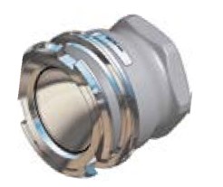
|
Flange 1B) |
Body Material 2) |
Seal 3) |
Weight ≈ |
Mann Tek Code No. |
||
|
O-Ring |
kg |
lbs |
||||
|
DN 150 PN 10 / 16 Type A |
Al |
Standard: FPM/FKM |
8,6 |
19.0 |
T645B1101 |
|
|
6" ASA 150 |
7,5 |
16.5 |
T6100B1101 |
|||
|
|
(Viton®) |
|||||
|
DN 150 PN 10 / 16 Type B |
|
22,4 |
49.4 |
T645B4401 |
||
|
SS |
Other on request. |
|||||
|
6" ASA 150 |
22,4 |
49.4 |
T6100B4401 |
|||
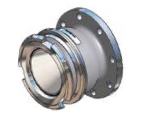
|
Connection 1) Inch/DN |
Body Material 2) |
Seal |
Weight ≈ |
Mann Tek Code No. |
|||
|
O-Ring 3) |
Thread Seal |
kg |
lbs |
||||
|
F 6" BSP |
Al |
Standard: FPM/FKM |
PUR |
22,3 |
49.2 |
S6110B1101B |
|
|
F 6" NPT |
— |
|
|
S6111B1101 |
|||
|
|
(Viton®) |
||||||
|
F 6" BSP |
|
PTFE |
|
|
S6110B4401A |
||
|
SS |
Other on request. |
||||||
|
F 6" NPT |
— |
45,0 |
99.2 |
S6111B4401 |
|||
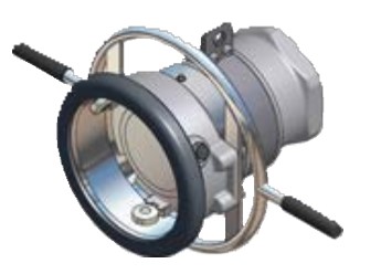
|
Flange 1B) |
Body Material 2) |
Seal 3) |
Weight ≈ |
Mann Tek Code No. |
||
|
O-Ring |
kg |
lbs |
||||
|
DN 150 PN 10 / 16 Type A |
Al |
Standard: FPM/FKM |
|
|
S645B1101 |
|
|
6" ASA 150 |
25,9 |
57.1 |
S6100B1101 |
|||
|
|
(Viton®) |
|||||
|
DN 150 PN 10 / 16 Type B |
|
|
|
S645B4401 |
||
|
SS |
Other on request. |
|||||
|
6" ASA 150 |
49,5 |
109.1 |
S6100B4401 |
|||
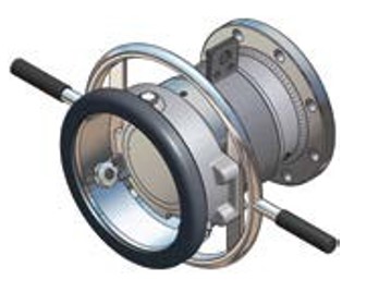
1A) F = Female thread, BSP = EN ISO 228, NPT = ANSI B1.20.1
1B) PN 10 / 16 / 25 / 40 = EN 1092 (types see page 44), ASA 150 = ANSI B16.5,150 psi
2) Material: Al = Aluminium, SS = Stainless Steel
3) Standard seal FPM/FKM. Alternative materials, e. g. EPDM, Chemraz®, Kalrez®, NBR or HNBR on request
Viton® is registred trademark of DuPont, DuPont Elastomers.
Tank Unit (Adapter) and Hose Unit (Coupler)
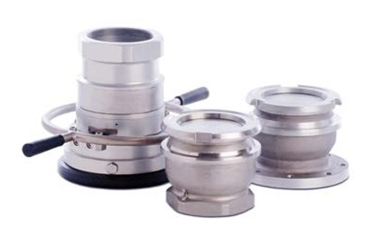
|
Material |
Maximum Working Pressure |
Test Pressure |
Minimum Burst Pressure |
|
Aluminium |
10 bar / 145 psi |
15 bar / 218 psi |
50 bar / 726 psi |
|
Stainless Steel |
16 bar / 232 psi |
24 bar / 348 psi |
80 bar / 1160 psi |
8" flanged inlet (or NPT thread)
Recommended for marine bunkering, ship to shore transfer, ship to ship transfer and ship to rig trans- fer or on any application where spillage needs to be minimized.
Petroleum products: gasoline, diesel, oil etc.
Chemical products: ethylene oxide,
propylene oxide, acrylonitrile, butadiene, ammonia, vinyl chloride, toluene, xylene, sulphuric acid, phenol etc.
Dry powder
Aluminium, brass/gunmetal, stainless steel, Hastelloy and PEEK. Other materials on request.
Standard seals FPM (Viton®), EPDM, FFKM (Chemraz®, Kalrez®), NBR. Other on request.
Allows maximum product transfer with minimal losses
7500 litres/minute (fuel)
To avoid product contamination caused by connecting a hose unit to the wrong tank unit, selective versions of the hose and tank units are available. Each unit has a number of selective positions, desig- nated by a coded part number according to the coup- ling size – specify when placing order. See page 32 ff.
Compatible with couplings of other manufacturers.
All hose units are supplied with an integrated swivel.
|
Flange 1) |
Body Material 2) |
Seal 3) |
Weight ≈ |
Mann Tek Code No. |
||
|
O-Ring |
kg |
lbs |
||||
|
DN 200 PN 10 Type A |
|
|
|
|
T8102A1101 |
|
|
DN 200 PN 16 Type A |
Al |
Standard: |
|
|
T8103A1101 |
|
|
8" ASA 150 |
|
|
T8105A1101 |
|||
|
|
FPM/FKM |
|||||
|
|
(Viton®) |
|||||
|
DN 200 PN 10 Type B |
|
|
|
T8102A4401 |
||
|
SS |
Other on request. |
|||||
|
DN 200 PN 16 Type B |
|
|
T8103A4401 |
|||
|
8" ASA 150 |
|
|
39,0 |
86.0 |
T8105A4401 |
|
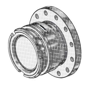
*) alternatively also available with NPT female inlet
|
Flange 1) |
Body Material 2) |
Seal 3) |
Weight ≈ |
Mann Tek Code No. |
||
|
O-Ring |
kg |
lbs |
||||
|
DN 200 PN 10 Type A |
|
|
|
|
S8102A1101 |
|
|
DN 200 PN 16 Type A |
Al |
Standard: |
|
|
S8103A1101 |
|
|
8" ASA 150 |
93,0 |
205.0 |
S8105A1101 |
|||
|
|
FPM/FKM |
|||||
|
|
(Viton®) |
|||||
|
DN 200 PN 10 Type B |
|
|
|
S8102A4401 |
||
|
SS |
Other on request. |
|||||
|
DN 200 PN 16 Type B |
|
|
S8103A4401 |
|||
|
8" ASA 150 |
|
|
93,0 |
205.0 |
S8105A4401 |
|
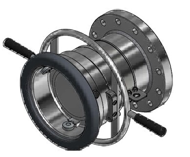
*) alternatively also available with NPT female inlet
1) PN 10 / 16 / 25 / 40 = EN 1092 (types see page 44), ASA = ANSI B16.5 (150 psi)
2) Material: Al = Aluminium, SS = Stainless Steel
3) Standard seal FPM/FKM. Alternative materials, e. g. EPDM, Chemraz®, Kalrez®, NBR or HNBR on request
Viton® is a registred trademark of DuPont, DuPont Elastomers.
To increase the lifespan of DDC tank units, dust caps should be used. They protect the couplings againstthe ingress of dirt and water.
Materials: polyethylene, aluminum, stainless steel or rubber. Supplied with cable attachment and eyelets (rubber design DN 40 - 50 with integrated eyelet).
With the exception of the simple rubber type, the caps feature a safeguard against inadvertent release: before removing the cap, a spring-loaded locking pin is pulled.
Polyethylene composite caps in sizes in sizes DN 40-80 mm include a patented design with lip seal to facilitate the handling.
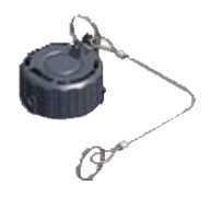
PE-Composite
Patent No. 000840780-0001

Aluminium
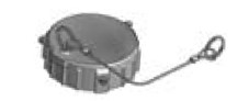
Stainless Steel
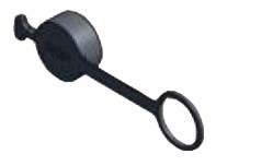
Rubber
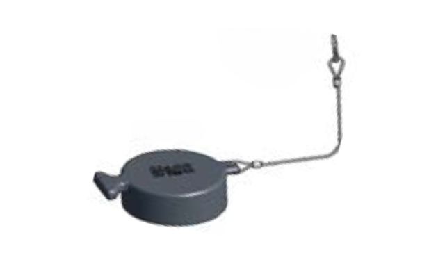
Rubber
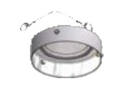
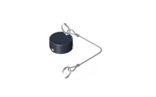
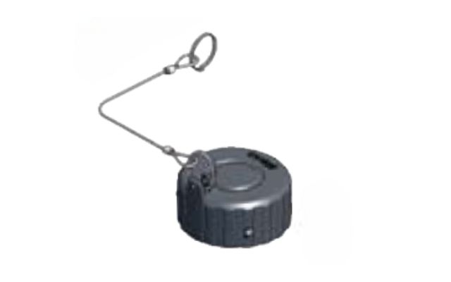
|
Inch / DN |
Material 1) |
Seal 2) |
Weight ≈ |
Mann Tek Code No. |
|
|
kg |
lbs |
||||
|
¾"-1" Ø 56 mm, DN 20-25 |
PE |
Standard: FPM (Viton®) |
0,1 |
0.29 |
C100A2201 |
|
Al |
0,2 |
0.49 |
C100A1101 |
||
|
SS |
0,6 |
1.30 |
C100A4401 |
||
|
1½-2" Ø 70 mm, DN 40-50 |
PE |
NBR |
0,1 |
0.2 |
C200E2202 |
|
Al |
Standard: FPM (Viton®) |
0,3 |
0.7 |
C200A1101 |
|
|
SS |
0,6 |
1.3 |
C200C4401 |
||
|
Rubber |
0,1 |
0.3 |
C200D1300 |
||
|
2½" Ø 105 mm, DN 65 |
PE |
NBR |
0,2 |
0,4 |
C300E2202 |
|
Al |
Standard: FPM (Viton®) |
|
|
C300A1101 |
|
|
SS |
1,5 |
3,3 |
C300C4401 |
||
|
3" Ø 119 mm, DN 80 |
PE |
NBR |
0,2 |
0,5 |
C400E2202 |
|
Al |
Standard: FPM (Viton®) |
|
|
C400A1101 |
|
|
SS |
|
|
C400C4401 |
||
|
Rubber |
— |
|
|
C400D1300 |
|
|
4" Ø 164 mm, DN 100 |
PE |
Standard: FPM (Viton®) |
0,2 |
0,5 |
C500E2202 |
|
Al |
1,2 |
2,5 |
C500B1101 |
||
|
SS |
2,5 |
5,5 |
C500C4401 |
||
|
6" Ø 238 mm, DN 150 |
PE |
|
|
C600A2201 |
|
|
Al |
1,6 |
3,4 |
C600A1101 |
||
|
SS |
|
|
C600A4401 |
||
|
8" Ø 272 mm, DN 200 |
Al |
|
|
C800B1101 |
|
|
SS |
|
|
C800B4401 |
||
1) Material: PE = Polyethylen-Composite, Al = Aluminium, SS = Stainless Steel, Rubber = NBR/PVC
2) Standard seal FPM/FKM or NBR. Alternative materials, e. g. EPDM, Chemraz®, Kalrez® or HNBR on request
Viton® is a registred trademark of DuPont, DuPont Elastomers.
used as third closing device according to ADR / RID, par. 6.8.2.2.2
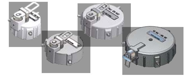
Mann Tek pressure caps have been developed to increase the safety of the operating personnel and improve leak protection.
In case of an upstream leakage (male coupling untight) or extensive pressue buildup within the tank outlet due to expanding gas, the cap will indicate it. The operator relieves the pressure by pressing the lever and can then safely remove the cap.
Features
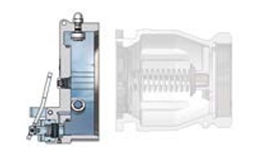
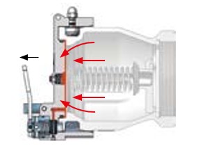
Pressure Indicator
(warns for overpressure)
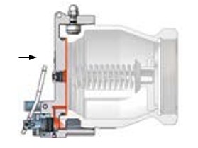
Press the handle for pressure relief, opening
|
Inch / DN |
Material of Body11) |
Seal 2) |
Working Pressure |
Mann Tek Code No. |
|
|
1½ - 2" Ø 70 mm, DN 40 - 50 |
SS |
|
25 bar / 363 psi |
R200A4401 |
|
|
2½" Ø 105 mm, DN 65 |
SS |
Standard: FPM (Viton®) |
25 bar / 363 psi |
R300A4401 |
|
|
3" Ø 119 mm, DN 80 |
SS |
25 bar / 363 psi |
R400A4401 |
||
|
Other on request. |
|||||
|
4" Ø 164 mm, DN 100 |
Al |
10 bar / 145 psi |
R500B1101 |
||
|
|
|||||
|
SS |
25 bar / 363 psi |
R500B4401 |
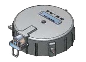
1) Material: Al = Aluminium, SS = Stainless Steel
3) Standard seal FPM/FKM or NBR. Alternative materials, e. g. EPDM, Chemraz® or Kalrez® on request
Viton® is a registred trademark of DuPont, DuPont Elastomers.
Suitable if a pressure tightness up to 10 bar - but no pressure relief - is required. Supplied with cable and mounting eyelets.
|
Inch / DN |
Material of Body 1) |
Seal 2) |
Weight ≈ |
Mann Tek Code No. |
||
|
kg |
lbs |
|||||
|
¾"-1" |
SS |
Standard: FPM (Viton®) Other on request. |
0,6 |
1,30 |
C100P4401 |
|
|
Ø 56 mm, DN 20-25 |
||||||
|
1½"-2" |
Al |
0,3 |
0.7 |
C200P1101 |
||
|
SS |
0,4 |
0.9 |
C200P4401 |
|||
|
Ø 70 mm, DN 40-50 |
||||||
|
2½" |
SS |
1,5 |
1.1 |
C300P4401 |
||
|
Ø 105 mm, DN 65 |
||||||
|
3" |
Al |
0,6 |
1.3 |
C400H1101 |
||
|
SS |
1,3 |
2.9 |
C400P4401 |
|||
|
Ø 119 mm, DN 80 |
||||||
|
4" |
SS |
2,9 |
6.4 |
C500P4401 |
||
|
Ø 164 mm, DN 100 |
||||||
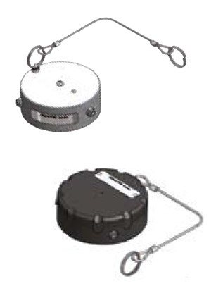
1) Material: Al = Aluminium, SS = Stainless Steel
2) Standard seal FPM/FKM or NBR. Alternative materials, e. g. EPDM, Chemraz® or Kalrez® on request
To increase the lifespan of couplers, dust plugs should be used. They protect the couplings against the ingress of dirt and water. Materials: polyethylene, aluminum, stainless steel. Supplied with cable attachment and eyelets.
|
Inch / DN |
Material of Body 1) |
Seal 2) |
Weight ≈ |
Mann Tek Code No. |
||
|
kg |
lbs |
|||||
|
¾"-1" |
PE |
Standard: FPM (Viton®) Other on request. |
0,1 |
0.1 |
P100A2201 |
|
|
Al |
0,1 |
0.3 |
P100A1101 |
|||
|
Ø 56 mm, DN 20-25 |
||||||
|
SS |
0,3 |
0.7 |
P100A4401 |
|||
|
1½-2" |
PE |
0,1 |
0.2 |
P200A2201 |
||
|
Al |
0,2 |
0.5 |
P200A1101 |
|||
|
Ø 70 mm, DN 40-50 |
||||||
|
SS |
0,2 |
0.6 |
P200A4401 |
|||
|
2½" |
PE |
0,2 |
0.5 |
P300A2201 |
||
|
Al |
0,6 |
1.2 |
P300A1101 |
|||
|
Ø 105 mm, DN 65 |
||||||
|
SS |
|
|
P300A4401 |
|||
|
3" |
PE |
0,1 |
0.2 |
P400A2201 |
||
|
Al |
0,7 |
1.6 |
P400A1101 |
|||
|
Ø 119 mm, DN 80 |
||||||
|
SS |
0,6 |
1.3 |
P400A4401 |
|||
|
4" |
PE |
0,2 |
0.4 |
P500B2201 |
||
|
Al |
0,3 |
0.7 |
P500B1101 |
|||
|
Ø 164 mm, DN 100 |
||||||
|
SS |
|
|
P500A4401 |
|||
|
6" |
PE |
|
|
P600A2201 |
||
|
Al |
1,2 |
0.4 |
P600A1101 |
|||
|
Ø 238 mm, DN 150 |
||||||
|
SS |
|
|
P600A4401 |
|||
|
8" Ø 272 mm, DN 200 |
Al |
1,2 |
0.4 |
P800A1101 |
||
|
SS |
|
|
P800A4401 |
|||
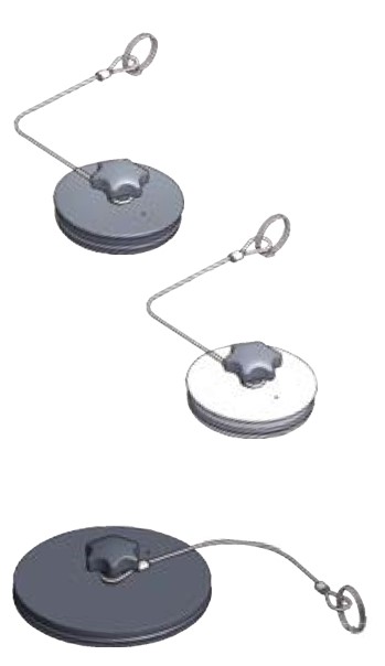
1) Material: PE = Polyethylene Composite, Al = Aluminium, SS = Stainless Steel
2) Standard seal FPM/FKM or NBR. Alternative materials, e. g. EPDM, Chemraz®, Kalrez® or HNBR on request
Viton® is a registred trademark of DuPont, DuPont Elastomers.
|
Coupling size
1" (Ø 56 mm) |
Material
Al |
Mann Tek Code-Nr. Tool 104-1 |
|
Tool 104-1-M18 *) |
||
|
SS |
Tool 104-4 |
|
|
Tool 104-4-M18 *) |
||
|
2" (Ø 70 mm) |
Al |
Tool 204-1 |
|
Tool 204-1-M18 *) |
||
|
SS |
Tool 204-4 |
|
|
Tool 204-4-M18 *) |
||
|
2½" (Ø 105 mm) |
Al |
Tool 304-1 |
|
Tool 304-1-M18 *) |
||
|
SS |
Tool 304-4 |
|
|
Tool 304-4-M18 *) |
||
|
3" (Ø 119 mm) |
Al |
Tool 404-1 |
|
Tool 404-1-M18 *) |
||
|
SS |
Tool 404-4 |
|
|
Tool 404-4-M18 *) |
||
|
4" (Ø 164 mm) |
Al |
Tool 504-1 |
|
Tool 504-1-M18 *) |
||
|
SS |
Tool 504-4 |
|
|
Tool 504-4-M18 *) |
||
|
6" (Ø 238 mm) |
Al |
Tool 604-1 |
|
Tool 604-1-M18 *) |
||
|
SS |
Tool 604-4 |
|
|
Tool 604-4-M18 *) |
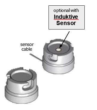
Parking adapters serve as a support for couplers when not in use.
They are screwed to the wall or other objects.
*) With Inductive sensor
Material: Al = Aluminium, SS = Stainless steel
To prevent accidental mixing of media, a selectivity sytem for DDCouplings is availa- ble. Tank units are equipped with slots, hose units with pins.
Depending on the size of the coupling and required compatibility, the number of possible 'selectivity positions' varies.
In case of questions please consult our sales team.
Tank Unit
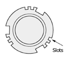
Hose Unit
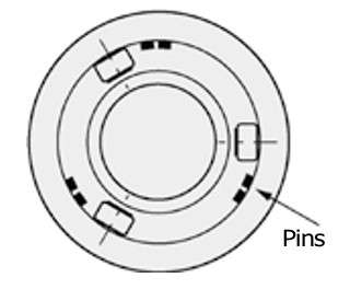
|
Product |
Size |
Position |
|
Avgas 100 / 130 |
2½", 3", 4" |
1 |
|
Avgas 108 / 135 |
2½", 3", 4" |
2 |
|
Avgas 115 / 145 |
2½", 3", 4" |
3 |
|
Avtur (Derd 2495) JP1, ATK, ATF 650. JET 'A' |
2½", 3", 4" |
4 |
|
Avtag (Derd 2486) JP4, ATG, JET 'B' |
2½", 3", 4" |
5 |
Example: Aircraft Refuelling
The major oil companies have agreed to use the following selectivity positions for aviation refuelling. For the 2½", 3" and 4" sizes.
Coupling diameter:
Ø56 mm (¾"-1")
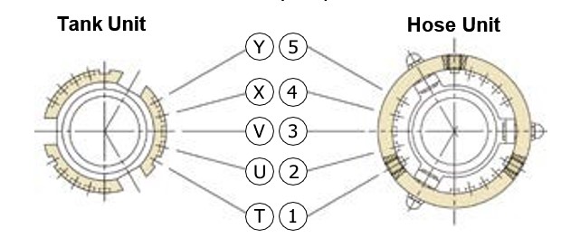
Selectivity system:
Mann Tek, Todo.
Each unit can be provided with selectivity according to two systems – with 5 or 10 positions (see chart).
When ordering, please add "/SEL" and the chosen selectivity to the Mann Tek Code No.
Examples: S103A4401/SEL 1 (T) or S103A4401/SEL 12 (TU)
|
Media |
Position |
|
acrylonitrile |
4 (X) |
|
ethylene oxide |
2 (U) |
|
Propylene eoxid |
3 (V) |
Selectivity positions for acrylonitrile, ethylene oxide and propylene oxide for 1"
With 5 Positions
T U V X Y
|
1 |
2 |
3 |
4 |
5 |
With 10 Positions
TU TV TX TY UV
|
12 |
13 |
14 |
15 |
23 |
|
24 |
25 |
34 |
35 |
45 |
UX UY VX VY XY
Coupling diameter: Ø 70 mm (1½"-2")
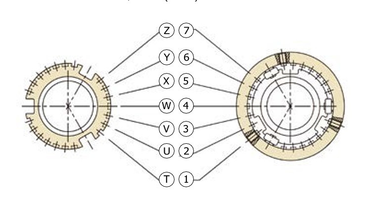
Selectivity System:
Mann Tek, Todo, Avery Hardoll, NATO STANAG 3756.
Each unit can be provided with selectivity according to two systems – with 7 or 21 positions (see chart).
When ordering, please add "/SEL" and the chosen selectivity to the Mann Tek Code No.
Examples: S210A4401A/SEL 1 (T) or S210A4401A/SEL 12 (TU)
|
Media |
Position |
|
acrylonitrile |
X (5) |
|
ethylene oxide |
V (3) |
|
propylene oxide |
W (4) |
Selectivity positions for acrylonitrile, ethylene oxide and propylene oxide for 2"
With 7 Positions
T U V W X Y Z
|
1 |
2 |
3 |
4 |
5 |
6 |
7 |
With 21 Positions
TU TV TW TX TY TZ UV UW UX UY UZ
|
12 |
13 |
14 |
15 |
16 |
17 |
23 |
24 |
25 |
26 |
27 |
|
34 |
35 |
36 |
37 |
45 |
46 |
47 |
56 |
57 |
67 |
|
VW VX VY VZ WX WY WZ XY XZ YZ
Coupling diameter: Ø 70 mm (1½"-2")
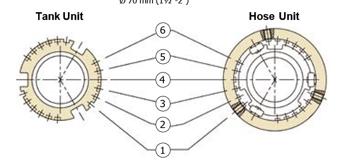
Selectivity System:
"Fort Vale"
Each unit can be provided with selectivity with 15 positions (see chart).
When ordering, please add the chosen selectivity to the Mann Tek Code No. Example: S210A4401A / FV-SEL 12
With 15 Positions
A B C D E F G H J K L M N P Q
|
12 |
13 |
14 |
15 |
16 |
17 |
23 |
24 |
25 |
26 |
34 |
35 |
36 |
45 |
56 |
Coupling diameter: Ø 105 mm (2½")
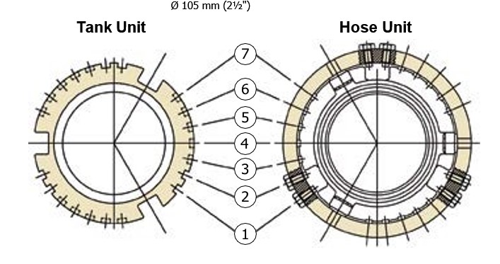
Selectivity System:
Mann Tek, Todo, NATO STANAG 3756,
Avery Hardoll
|
Each unit can be provided with selectivity according to |
|
two systems – with 7 or 21 positions (see chart). |
|
|
|
When ordering, please add "/SEL" and the chosen |
|
Examples: S312A4401/SEL 1 or S312A4401/SEL 12 (A) |
With 7 Position
|
1 |
2 |
3 |
4 |
5 |
6 |
7 |
With 21 Positions
|
A |
B |
C |
D |
E |
F |
G |
H |
I |
K L |
|
|
|
|
|
|
|
|
|
|
|
|
M |
N |
P |
Q |
R |
S |
T |
U |
V |
W |
Coupling diameter: Ø 105 mm (2½")
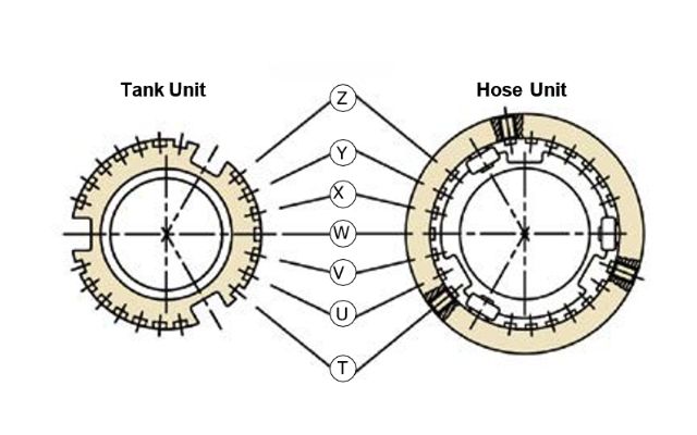
Selectivity System:
Fulcrum
Each unit can be provided with selectivity according to two systems – with 7 or 21 positions (see chart).
When ordering, please the chosen selectivity to the Mann Tek Code No. Examples: S312A4401/SEL 1 or S312A4401/SEL 12 (A)
With 7 Positions
|
1 |
2 |
3 |
4 |
5 |
6 |
7 |
With 21 Positions
|
TU |
TV |
TW |
TX |
TY |
TZ |
UV |
|
UW |
UX |
UY |
UZ |
VW |
VX |
VY |
|
VZ |
WX |
WY |
WZ |
XY |
XZ |
YZ |
Coupling diameter: Ø 119 mm (3")
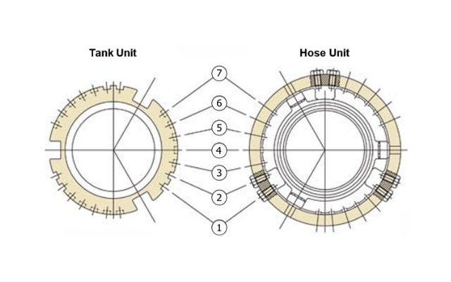
Selectivity System:
Mann Tek, Todo, NATO STANAG 3756,
Avery Hardoll
Each unit can be provided with selectivity according to two systems – with 7 or 21 positions (see chart).
When ordering, please add "/SEL" and the chosen selectivity to the Mann Tek Code No.
Examples: S414A4401/SEL 1 bzw. S414A4401/SEL 12 (A)
With 7 Positions
|
1 |
2 |
3 |
4 |
5 |
6 |
7 |
With 21 Positions
A B C D E F G H I K L
|
12 |
13 |
14 |
15 |
16 |
17 |
23 |
24 |
25 |
26 |
27 |
|
34 |
35 |
36 |
37 |
45 |
46 |
47 |
56 |
57 |
67 |
|
M N P Q R S T U V W
Coupling diameter: Ø 164 mm (4")
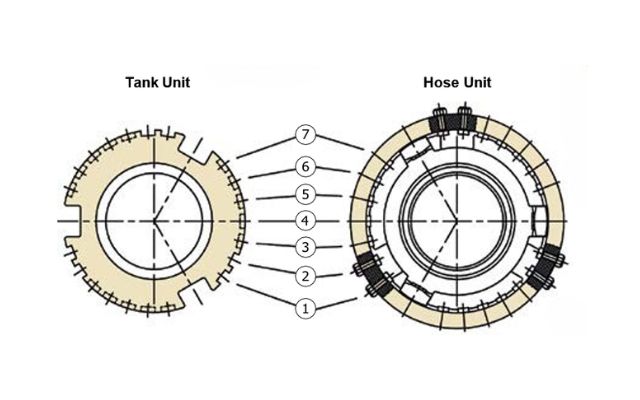
Selectivity System:
Mann Tek, Todo, NATO STANAG 3756, Avery Hardoll
|
Each unit can be provided with selectivity according to |
|
two systems – with 7 or 21 positions (see chart). |
|
|
|
When ordering, please add "/SEL" and the chosen selectivity to the Mann Tek code No. |
|
Examples: S516A4401/SEL 1 or S516A4401/SEL 12 (A) |
|
Media |
Position |
|
acrylonitrile |
36 (P) |
|
ethylene oxide |
34 (M) |
|
propylene oxide |
35 (N) |
Selectivity positions for acrylonitrile, ethylene oxide and propylene oxide for 4".
With 7 Positions
|
1 |
2 |
3 |
4 |
5 |
6 |
7 |
With 21 Positions
|
A |
B |
C |
D |
E |
F |
G |
H |
I |
K L |
|
|
|
|
|
|
|
|
|
|
|
|
M |
N |
P |
Q |
R |
S |
T |
U |
V |
W |
Coupling diameter: Ø 238 mm (6")
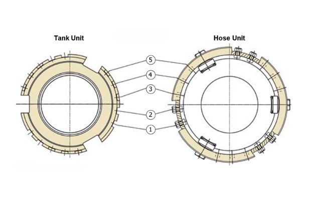
Selectivity System:
Compatible with TODO (Gardner Denver).
Each unit can be provided with 10 selectivity positions (see chart).
When ordering, please add "/SEL" and the chosen selectivity to the Mann Tek Code No.
Examples: S645B4401/SEL 12
With 10 Positions
|
12 |
13 |
14 |
15 |
23 |
|
24 |
25 |
34 |
35 |
45 |
A = API Adapter
AV = Tank Unit EN 13081 ( special version )
B = Ball Valve
C = Dust Cap
CG = Dust Cap LPG
D = Swivel
E = Tank Unit with pressure valves
F = Hose Unit ( ISO 45 )
G = Tank Unit ( ISO 45 )
GS = Tank Unit ( ISO 45 ) with selectivity
H = Sampling Vent & Drain Unit I = Dust Plug ISO 45
K = Dust Cap ISO 45
L = Tank Unit LPG
LC = Tank Unit Cryogenic M = Hose Unit LPG
MC = Hose Unit Cryogenic N = Break Away Pin
NC = Break Away Pin Cryogenic O = Break Away Wire
P = Dust Plug
R = Pressure Cap
RG = Pressure Cap LPG
S = Hose Unit ( STANAG 3756 )
SN = Hose Unit int. Break Away Pin SO = Hose Unit int. Break Away Wire
T = Tank Unit ( STANAG 3756 )
U = Filter / Sight Glass
V = Dust Plug LPG WA = Hose Fittings
01 = ¾" BSP ( female )
02 = ¾" NPT ( female )
03 = 1" BSP ( female ) 04 = 1" NPT ( female )
05 = 1¼" BSP ( female )
06 = 1¼" NPT ( female )
07 = 1½" BSP ( female )
08 = 1½" NPT ( female )
09 = 1¾" BSP ( female )
10 = 2" BSP ( female )
11 = 2" NPT ( female )
12 = 2½" BSP ( female )
13 = 2½" NPT ( female )
14 = 3" BSP ( female )
15 = 3" NPT ( female )
16 = 4" BSP ( female )
17 = 4" NPT ( female )
18 = Flange undrilled Ø 156
19 = Flange undrilled Ø 165
20 = Flange undrilled Ø 210
21 = Flange undrilled Ø 230
22 = Flange undrilled Ø 254
23 = Flange DN 25 PN 10 / 16
24 = Flange DN 25 PN 25 / 40
25 = Flange DN 32 PN 10 / 16
26 = Flange DN 32 PN 25 / 40
27 = Flange DN 40 PN 10 / 16
28 = Flange DN 40 PN 25 / 40
29 = Flange DN 50 PN 25 / 40*
30 = Flange DN 50 PN 10 / 16
31 = Flange DN 50 PN 25 / 40
32 = Flange DN 65 PN 25 / 40*
33 = Flange DN 65 PN 10 / 16
34 = Flange DN 65 PN 25 / 40
35 = Flange DN 80 PN 25 / 40*
36 = Flange DN 80 PN 10 / 16
37 = Flange DN 80 PN 25 / 40
38 = Flange DN 100 PN 25 / 40*
39 = Flange DN 100 PN 10 / 16
40 = Flange DN 100 PN 25 / 40
41 = Flange DN 125 PN 6
42 = Flange DN 125 PN 10 / 16
43 = Flange DN 125 PN 25 / 40
44 = Flange DN 150 PN 6
45 = Flange DN 150 PN 10 / 16
46 = Flange DN 150 PN 25 / 40
47 = Flange DN 20 PN 10 / 16
48 = Flange DN 20 PN 25 / 40
49 = Flange ¾" ANSI Class 150
50 = Flange ¾" ANSI Class 300
51 = Flange 1" ANSI Class 150
52 = Flange 1" ANSI Class 300
53 = Flange 1¼" ANSI Class 150
54 = Flange 1¼" ANSI Class 300
55 = Flange 1½" ANSI Class 150
56 = Flange 1½" ANSI Class 300
57 = Flange 2" ANSI Class 150
58 = Flange 2" ANSI Class 300
59 = Flange 2½" ANSI Class 150
60 = Flange 2½" ANSI Class 300
61 = Flange 3" ANSI Class 150
62 = Flange 3" ANSI Class 300
63 = Flange 4" ANSI Class 150
64 = Flange 4" ANSI Class 300
65 = Flange TW 1 (3" - DN 80)
66 = Flange TW 3 (4" - DN 100)
67 = Flange 3" T.T.M.A.
68 = Flange 4" T.T.M.A.
69 = ¾" BSP ( male )
70 = ¾" NPT ( male )
71 = 1" BSP ( male )
72 = 1" NPT ( male )
73 = 1¼" BSP ( male )
* EN 1092-1:2001 Type E: Spigot
74 = 1¼" NPT ( male )
75 = 1½" BSP ( male )
76 = 1½" NPT ( male )
77 = 1¾" BSP ( male )
78 = 2" BSP ( male )
79 = 2" NPT ( male )
80 = 2½" BSP ( male )
81 = 2½" NPT ( male )
82 = 3" BSP ( male )
83 = 3" NPT ( male )
84 = 4" BSP ( male )
85 = 4" NPT ( male )
86 = Weld.flange 2" Ø 60,5 ID
87 = Flange TW 1 ( 2" DN 50 )
88 = Weld.flange 2" Ø 50 - Ø 70 ( flat )
89 = Weld.flange 2" Ø 57 ( int. chamfer )
90 = Weld.flange 2" Ø 60 (outer chamfer )
91 = Weld.flange 3" Ø 75 - Ø 90 (flat)
92 = Weld.flange 3" Ø 76 ( int. chamfer )
93 = Weld.flange 3" Ø 89 ( outer chamfer )
94 = Weld.flange 4" Ø 100 - Ø 120 (flat)
95 = Weld.flange 4" Ø 102 ( int. chamfer )
96 = Weld.flange 4" Ø 108 ( int. chamfer )
97 = Weld.flange 4" Ø 114 ( outer chamfer )
98 = Flange TW 1 (2" - DN 50)
with drain connection
99 = Flange DN 150 PN 25
100 = Flange 6" ANSI Class 150
101 = Flange 6" ANSI Class 300
102 = Flange DN 200 PN 10
103 = Flange DN 200 PN 16
104 = Flange DN 200 PN 25
105 = Flange 8" ANSI Class 150
106 = Flange 8" ANSI Class 300
107 = Flange Square ISO 45
108 = S60 x 6 ( female )
109 = S60 x 6 ( male )
110 = 6" BSP ( female )
111 = 6" NPT ( female )
112 = W2" - 7 ( female )
113 = Weld.flange 3" Ø 92 inner
114 = Square flange, 4 holes
115 = 6" BSP ( male )
116 = 6" NPT ( male )
117 = 8" NPT ( female )
118 = 4" Victaulic
119 = Flange DN 50 PN 25 / 40**
120 = Flange DN 65 PN 25 / 40**
121 = Flange DN 80 PN 25 / 40**
122 = Flange DN 100 PN 25 / 40**
123 = W2" - 7 ( male )
124 = 5" NPT ( female )
125 = 5" NPT ( male )
126 = Flange DN 100 PN 6
127 = Flange DN 80 PN 6
128 = Flange DN 65 PN 6
129 = Flange DN 50 PN 6
130 = Flange 8" ANSI Class 600
131 = W90 x 1/6" ( female )
132 = ½" NPT ( female )
133 = ½" BSP ( female )
134 = Flange Ø 184.2, 6 holes
135 = Flange TW 7 (6" - DN 150)
136 = 4" ASSPT ( female )
137 = Triclamp DN 25
138 = M54 x 1,5 ( female )
139 = Triclamp DN 50
140 = Weld.flange Ø 73 ( outer chamfer )
141 = 3" Victaulic
142 = Flange 5" ANSI Class 150
143 = 3" Ball valve
144 = 2" Victaulic
145 = 3" BSPT ( male )
** EN 1092-1:2001 Type F
146 = 5" Victaulic
147 = 2" BSPT ( female )
148 = 2" BSPT ( male )
149 = 1½" Victaulic
150 = 2½" Victaulic
151 = Flange 1" DIN 11864-2
152 = Flange 2" DIN 11864-2
153 = Flange Ø 135, 8 x M6
154 = 4" BSPT ( female )
155 = 4" BSPT ( male )
156 = Weld flange 2" Ø 61,5 ID
157 = 3" BSPT ( female )
158 = Weld end 1½" Ø 48 OD
159 = Thread TR 57 x 4
160 = Flange 2" BS10 Table D
161 = Flange 12" ANSI Class 150
162 = Flange 10" ANSI Class 150
163 = Flange DN 250 PN 16
164 = M130 x 6 ( female )
165 = Flange 10" ANSI Class 300
166 = ACME 1¼" ( female )
167 = ACME 1¾" ( female )
168 = ACME 2¼" ( female )
169 = ACME 3¼" ( female )
170 = ACME 1¼" ( male )
171 = ACME 1¾" ( male )
172 = ACME 2¼" ( male )
173 = ACME 3¼" ( male )
174 = Weld.flange Ø 76 ( outer chamfer )
175 = Flange DN 15 PN 10 / 16
176 = Flange DN 15 PN 25 / 40
177 = M130 x 6 ( male )
178 = Flange 6" T.T.M.A.
179 = Flange DN 80 PN 25 / 40***
180 = ½" NPT ( male )
181 = ½" BSP ( male )
182 = 5" BSP ( female )
183 = 5" BSP ( male )
184 = Weld end 8" Ø 219 OD
185 = Weld end 6" Ø 168 OD
186 = Flange DN 250 PN 25
187 = Flange 2" T.T.M.A.
188 = Flange 3" BS10 Table D
189 = Flange ½" ANSI Class 150
190 = Flange 1" ANSI Class 150 Flat Face
191 = Flange 12" ANSI Class 300
192 = Flange DN 250 PN 10
193 = Weld end Ø 114 Schedule 40
194 = Weld end Ø 114 Schedule 80
195 = 6" Victaulic
196 = 1" Victaulic
197 = DN 125 JIS 5K
198 = DN 100 JIS 5K
199 = DN 80 JIS 5K
200 = DN 50 JIS 5K
201 = DN 40 JIS 5K
202 = Flange 2" DIN 11864-3
203 = 3½" BSP ( female )
204 = Flange Ø 110, Ø 86 / Ø 5.5 ( 6x )
205 = Weld end Ø 60 Schedule 80
206 = Weld end Ø 89 Schedule 40
207 = Weld end Ø 89 Schedule 80
208 = Flange DN 25 PN 6
209 = Flange DN 32 PN 6
210 = Flange DN 40 PN 6
211 = DN 125 JIS 10K
212 = DN 100 JIS 10K
213 = DN 80 JIS 10K
214 = DN 50 JIS 10K
215 = DN 40 JIS 10K
216 = Flange DN 80, holes Ø 14 ( 6x )
217 = Flanges 5" ANSI Class 300
No part of this leaflet may be reproduced in any form or by any means without permission in writing fr om the publisher
NOTE: When swivels are chosen (first sign: D), the second and the third sign indicate thread side 1 one, the fourth and the fifth sign the second outlet indicate thread side 2.
Design may change without notice.
A = Version No. 1 (machined from bar)
B = Version No. 2 (casted)
C = Version No. 3 (kokill casted)
D = Sep. piston guide
E = Injection moulded
F = 6" Flange Hydrant
G = Drain connection
H = Leaf spring lock
I = Bent (dropped) Tank Unit, short ( 15° )
J = Bent (dropped) Tank Unit ( 15° )
K = Short Tank Unit / Swivel N = Non Return Valve
P = Pressure ( Custom )
S = Sight Glass
T = Transparent
U = Stop before disconnected
1 = Aluminium
2 = Brass
3 = Steel
4 = Edelstahl 1.4408 ( AISI 316 )
5 = Edelstahl 1.4301 ( AISI 304 )
6 = Titan
7 = Hastelloy
8 = PVDF
9 = PEEK
1 = Aluminium
2 = Brass
3 = Steel
4 = Stainless steel A4 ( 316 )
5 = Stainless steel 1.4301
6 = Titan
7 = Hastelloy
8 = PVDF
9 = PEEK
K = Inconel
A = Flat Seal, Teflon® ( PTFE )
B = Flat Seal, Vulkollan® ( PUR)
C = 2-Way Ball Valve
D = Flat Seal, Viton® ( FPM) DA = Double Acting ( Ball Valve)
M = Two-Step Cam Curve
N = No Branding
U20 = Pressure Bleeding valve 20 bar
V = Locked Hose Unit
NA = Ball Valve w. square trunnion (no actuator) W = Swivel with double ball valve
D = Flat Seal, Viton® ( FPM) DA = Double Acting ( Ball Valve)
P = Pressure Equalizing Valve
Q = Sampling Vent & Drain Unit with
X = Special surface treatment Z = Excentric Tank Unit
E = Tank Unit with short piston reduced bore diameter ( Argus, Hydrant ) -RA = Racing
F = Flange thickness acc. to standard
G = Flat Seal, Hypalon®
H = Flat Seal, Nitrile ( NBR) I = Emco compatible
J = Flat Seal, EPDM
K = Adapter with locked piston guide
L = Locked thread (maggot screw)
R = Hose Unit with int. Break Away
S = Sampling Vent & Drain Unit, only with one ball valve
SR = Spring Return ( Ball Valve)
T = TW-Flange extended circles
U = Pressure Bleeding Valve 16 bar U5 = Pressure Bleeding Valve 5 bar
-LC = Locking Cap
-S = FEP O-Ring in Hose Unit swivel
-ST = Steam
-XL = Oversized swivel
-45 = 45 Mesh
-60 = 60 Mesh
-10 = 100 Mesh
Example:
2" (Ø 70 mm) Hose Unit (Coupler), female thread

Selection of registred trade names from BASF, Bayer AG, B.F. Goodrich, Chemische Werke Hüls, Daikin, Dow Company, DSM, DuPont, DuPont Dow Elastomers, Esso Chemie, Hercules, Hoechst AG, Montedison, Monteflous, Nippon Zeon, Polysar LTD., Rhone Poulenc, 3M Company, Wacker Chemie, Precision Polymer Engineering Ltd.
Couplings with Special Flanges
On request we manufacture all combinations of flange thickness / holes and length
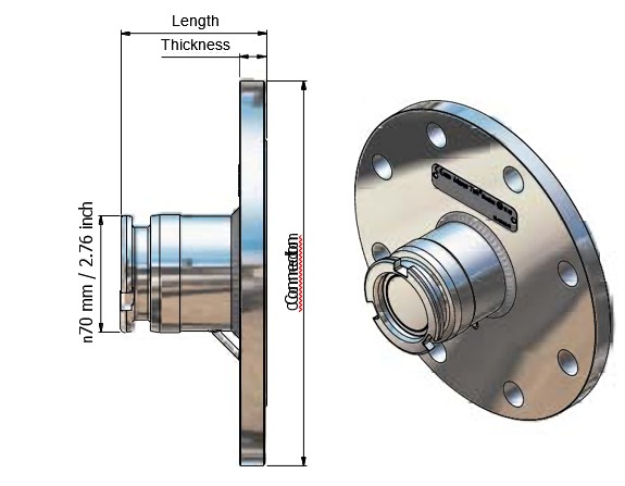
Example: 2" (Ø 70 mm) tank unit (adapter) with flange 4" ANSI 150 psi, Code No: T263A4401
Tank Unit with Short Piston
When coupled, the piston spindle does not protrude. This special type is useful e. g. for the direct connection to ball vallves.
Example Mann Tek Code No.: T230B1101E
Tank Unit with Drain Connection
Für easy venting and sampling.
Available for all tank units with flange.
Example Mann Tek Code No.: T298G1101 (f. TW1 Flansch)
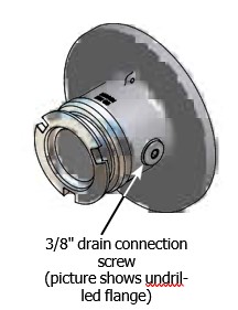
Tank unit (adapter) with excentrical flange, available in sizes from 1" to 6".
Example 2" (Ø 70 mm) tank unit with excentrical flange 4" ASA 150, Mann Tek Code-Nr.: T263A4401Z
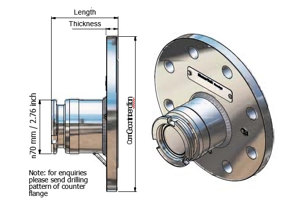
Traditional Flange
.jpg)
Excentrical Flange
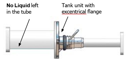
Type E (Spigot) / Type F (Recess)
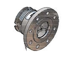
Tank Unit
Flange EN 1092-1
Type E (Spigot)
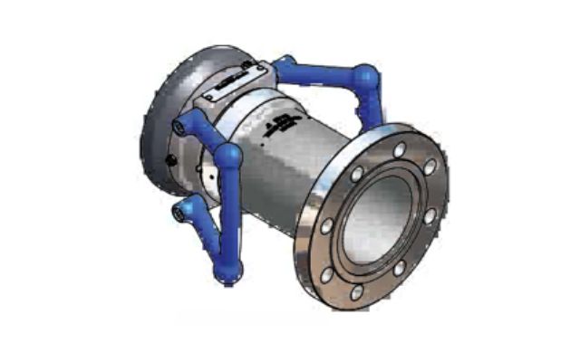
Hose Unit
Flange EN 1092-1
Type F (Recess)
Standard flange connections are usually executed with sealing surface Type A (Flat Face ) oder Type B ( Raised Face ), see page 44.
Current alternatives are Type E ( Spigot ) and Type F ( Recess ), which are used from some road and rail tank manufacturers.
All DDCouplings can be manufactured with grooved pipe ends, compatible with the Victaulic system.
Suitable e. g. for military and offshore applications.
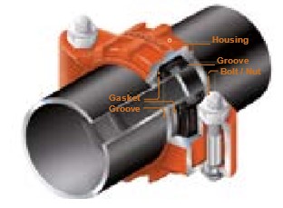
Victaulic® is a registred brand name of Victaulic Europe
Example Mann Tek Code-Nr. S2144A1101
After the coupling the connection is automatically locked and can not loosen unintentionally. Pulling ring version LD-S2 or lever version L-S2, available for hose units (couplers) of any size.
4" hose unit withlocking device (lever) 2" hose unit with locking device (pulling ring)
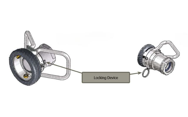
Example: Addition to Mann Tek Code-Nr L-S5 Example: Addition to Mann Tek Code-Nr LD-S2
Ground cables serve for the safe electrostatic dissipation of electrical currents (potential equalization).
They are prescribed for some applications, e. g. for air- craft refuelling.
Materials: Cable stainless with plastic coatingl, crocodile clamp brass, including assembly.
Mann Tek Code No. G-F3-12-XXX.
When ordering please substitute XX with the required length (mm).
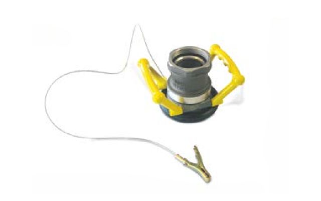
Where there is a risk of excessive force on the hose due to unexpected movement between the loading and unloading station.
For these application DDCouplings with integrated SBCouplings (Safety Break Away) are available.
Pleas add 'N' to the Mann Tek Code No., Example: SN211A4401.
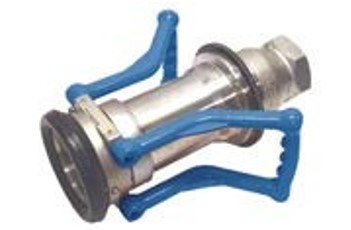
The medium can not flow back when the pump switches off while the coupling is still connected. Suitable for some wet hose applications.
Example Mann Tek Code-Nr.: S210N1101B
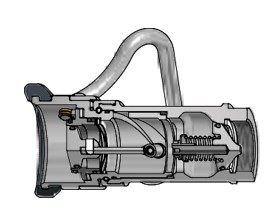
2" (Ø 70 mm) coupler in 'big mouth' special version, com- patible with older Emco Wheaton tank units.
Example Mann Tek
Code No.: S210A1101BI
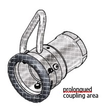
For the emergency unloading of rail or road tankers, the swivel of the coupler must be blocked for a fast connection with standard thread connections without tools.
Several different versions are available from Mann Tek.
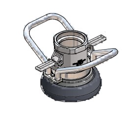
Extended handle for 2", 2½" and 3" Hose unit
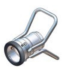
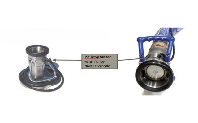
Electronic Sensor
The sensor is detecting the position of the driving plate inside the hose unit.
No modifi cation on the tank unit is needed. That makes it possible to identify if the hose unit is connected to a tank unit and if they are in an open position.
Z : Option Sensor
S1 : for 1" coupling
S3 : for 2½" coupling
S5 : for 4" coupling
44 : Housing material Stainless Steel
A1 : DC-PNP
S2 : for 2" coupling
S4 : for 3" coupling
S6 : for 6" coupling
A2 : NAMUR Standard
Available with ATEX on request II 2G
Example: additional Mann Tek Code No.
... + Z-S1-44-A1
Only for special operating conditions where there is the risk of excessive pressure increase through warming in the pipe / hose system.
To protect the equipment, the optional pressure bleeding valve opens at a predetermined pressure limit.
Other applications: adapter pieces between different DDCouplings, hose assemblies with DDCouplings or DACouplings on both sides, e. g. military applications (logistic supply lines).
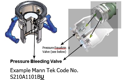
If liquid can get trapped in the tank unit during operation so that it can not escape, there is the risk that the tank unit is damaged during coupling.
Process engineering solution: open valves behind the tank unit to relieve the trapped liquid.
Technical solution: the optional pressure equalizing valve relieves the pressure during coupling into the hose unit.
Example Mann Tek Code No. S210A1101BP
.jpg)
for Petroleum Based Products
Tank an hose units in size 2½" BSP/NPT or 3" BSP/NPT are available with an additional sight glass with integrated strainer. During operation it is easy to see when the strainer shall be cleaned.
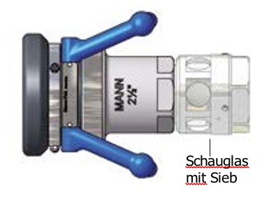
– easy service of the strainer due to quick connection-
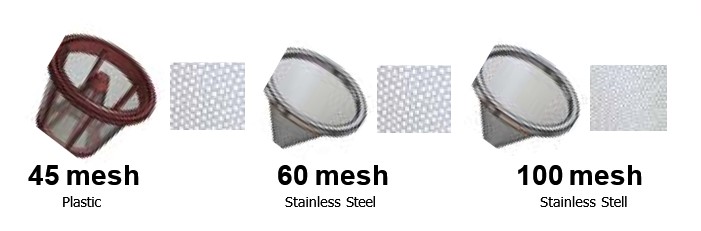
Three different screen sizes are available,
45 mesh (350 µm), 60 mesh (250 µm) or 100 mesh (150 µm).
Example for Code No. 'Sight Glass with Strainer: U1280S1101-XX – when ordering, replace XX with -45 for 45 mesh, -60 for 60 mesh, -10 for 100 mesh.
For a clear assignment of coupling and medium, the body, flange and handles of our couplings are available in any required colour.
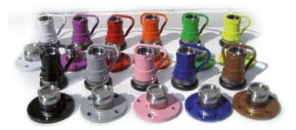
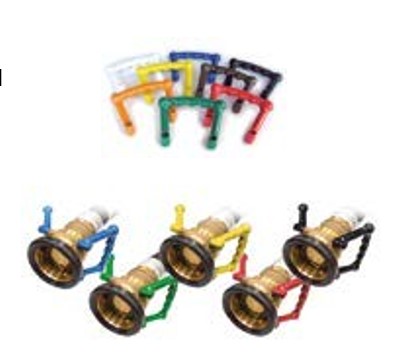
DDCouplings are available with aseptic flanges to DIN 11864-2 or Triclamp flange connection.
Applications: for foodstuffs/beverages, fine chemicals, filter and water treatment plants.
Note: not suitable for pharmaceutical media with highest requirements to sterility.
On request for the mentioned coupling a test according GMP can be effected.
Tank and Hose Units with Aseptic Flange to DIN 11864-2
FDA conform seals
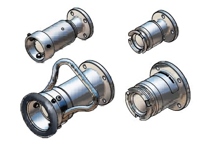
Tank and Hose Units with Triclamp Connection to DIN 32676
FDA conforme seals
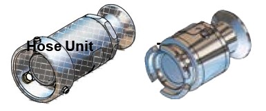
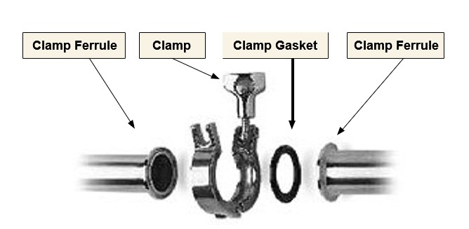
DDCouplings can be installed and dismounted without special tools, with standard wrenches.
Additionally, below mentioned tools are helpful to open the piston (the valve plates) to empty the system:

Wrench size to install or dismount tank and hose units:
|
for Coupling |
Wrench Size |
|
1" |
SW 50 mm |
|
2" |
SW 65 mm |
|
2½" |
SW 85 mm |
|
3" |
SW 100 mm |
|
4" |
Tank Unit - 125 mm Hose Unit - 130 mm |
|
6" |
SW 190 mm |
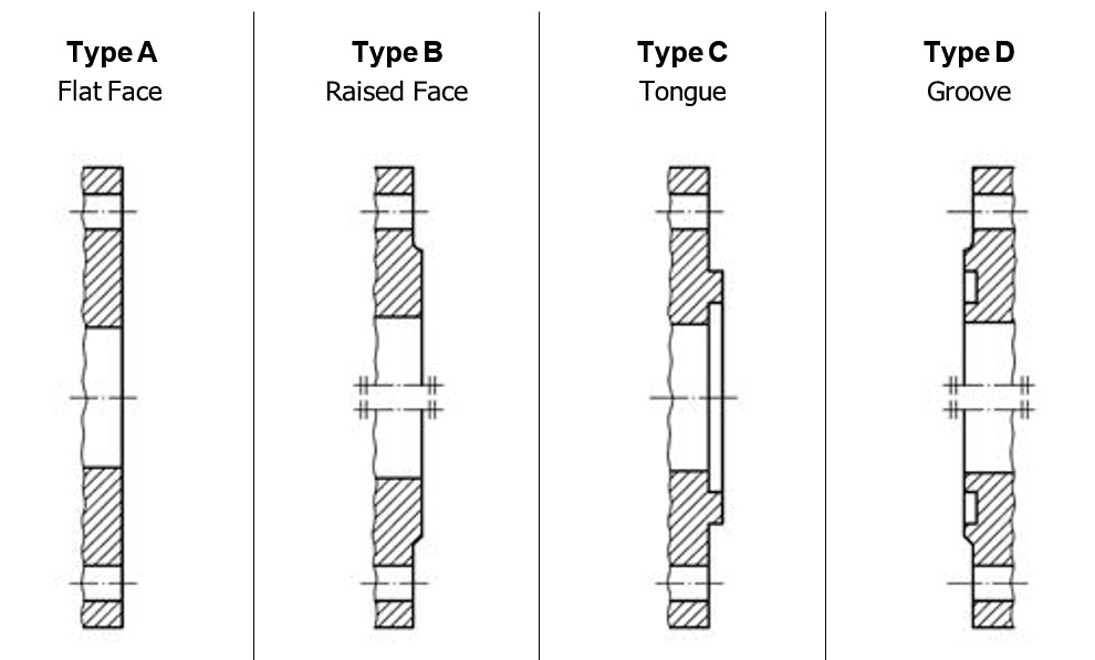
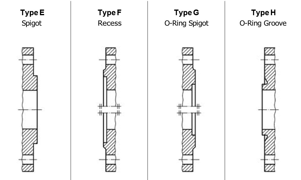
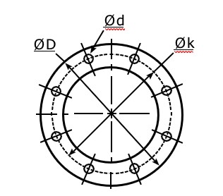
D = Diameter
Ø k = Centre Diameter
n = Number of Holes
Ø d = Hole Diameter
|
EN 1092-1 |
|
DN |
PN 10 |
PN 16 |
PN 25 |
PN 40 |
||||||||||||
|
Ø D |
Ø k |
n |
Ø d |
Ø D |
Ø k |
n |
Ø d |
Ø D |
Ø k |
n |
Ø d |
Ø D |
Ø k |
n |
Ø d |
|
|
20 |
mm |
105 |
75 |
4 |
14 |
105 |
75 |
4 |
14 |
105 |
75 |
4 |
14 |
105 |
75 |
4 |
14 |
|
inch |
4.13 |
2.95 |
0.55 |
4.13 |
2.95 |
0.55 |
4.13 |
2.95 |
0.55 |
4.13 |
2.95 |
0.55 |
|||||
|
25 |
mm |
115 |
85 |
4 |
14 |
115 |
85 |
4 |
14 |
115 |
85 |
4 |
14 |
115 |
85 |
4 |
14 |
|
inch |
4.53 |
3.35 |
0.55 |
4.53 |
3.35 |
0.55 |
4.53 |
3.35 |
0.55 |
4.53 |
3.35 |
0.55 |
|||||
|
32 |
mm |
140 |
100 |
4 |
18 |
140 |
100 |
4 |
18 |
140 |
100 |
4 |
18 |
140 |
100 |
4 |
18 |
|
inch |
5.51 |
3.94 |
0.71 |
5.51 |
3.94 |
0.71 |
5.51 |
3.94 |
0.71 |
5.51 |
3.94 |
0.71 |
|||||
|
40 |
mm |
150 |
110 |
4 |
18 |
150 |
110 |
4 |
18 |
150 |
110 |
4 |
18 |
150 |
110 |
4 |
18 |
|
inch |
5.91 |
4.33 |
0.71 |
5.91 |
4.33 |
0.71 |
5.91 |
4.33 |
0.71 |
5.91 |
4.33 |
0.71 |
|||||
|
50 |
mm |
165 |
125 |
4 |
18 |
165 |
125 |
4 |
18 |
165 |
125 |
4 |
18 |
165 |
125 |
4 |
18 |
|
inch |
6.50 |
4.92 |
0.71 |
6.50 |
4.92 |
0.71 |
6.50 |
4.92 |
0.71 |
6.50 |
4.92 |
0.71 |
|||||
|
65 |
mm |
185 |
145 |
4 |
18 |
185 |
145 |
4 |
18 |
185 |
145 |
8 |
18 |
185 |
145 |
8 |
18 |
|
inch |
7.28 |
5.71 |
0.71 |
7.28 |
5.71 |
0.71 |
7.28 |
5.71 |
0.71 |
7.28 |
5.71 |
0.71 |
|||||
|
80 |
mm |
200 |
160 |
8 |
18 |
200 |
160 |
8 |
18 |
200 |
160 |
8 |
18 |
200 |
160 |
8 |
18 |
|
inch |
7.87 |
6.30 |
0.71 |
7.87 |
6.30 |
0.71 |
7.87 |
6.30 |
0.71 |
7.87 |
6.30 |
0.71 |
|||||
|
100 |
mm |
220 |
180 |
8 |
18 |
220 |
180 |
8 |
18 |
235 |
190 |
8 |
22 |
235 |
190 |
8 |
22 |
|
inch |
8.66 |
7.09 |
0.71 |
8.66 |
7.09 |
0.71 |
9.25 |
7.48 |
0.87 |
9.25 |
7.48 |
0.87 |
|||||
|
125 |
mm |
250 |
210 |
8 |
18 |
250 |
210 |
8 |
18 |
270 |
220 |
8 |
26 |
270 |
220 |
8 |
26 |
|
inch |
9.84 |
8.27 |
0.71 |
9.84 |
8.27 |
0.71 |
10.63 |
8.66 |
1.02 |
10.63 |
8.66 |
1.02 |
|||||
|
150 |
mm |
285 |
240 |
8 |
22 |
285 |
240 |
8 |
22 |
300 |
250 |
8 |
26 |
300 |
250 |
8 |
26 |
|
inch |
11.22 |
9.45 |
0.87 |
11.22 |
9.45 |
0.87 |
11.81 |
9.84 |
1.02 |
11.81 |
9.84 |
1.02 |
|||||
|
200 |
mm |
340 |
295 |
8 |
22 |
340 |
295 |
12 |
22 |
360 |
310 |
12 |
26 |
375 |
320 |
12 |
30 |
|
inch |
13.39 |
11.61 |
0.87 |
13.39 |
11.61 |
0.87 |
14.17 |
12.20 |
1.02 |
14.76 |
12.60 |
1.18 |
|||||
|
250 |
mm |
395 |
355 |
12 |
22 |
405 |
355 |
12 |
26 |
425 |
370 |
12 |
30 |
450 |
385 |
12 |
33 |
|
inch |
15.55 |
13.98 |
0.87 |
15.94 |
13.98 |
1.02 |
16.73 |
14.57 |
1.18 |
17.72 |
15.16 |
1.30 |
|||||
|
300 |
mm |
445 |
400 |
12 |
22 |
460 |
410 |
12 |
26 |
485 |
430 |
16 |
30 |
515 |
450 |
16 |
33 |
|
inch |
17.52 |
15.75 |
0.87 |
18.11 |
16.14 |
1.02 |
19.09 |
16.93 |
1.18 |
20.28 |
17.65 |
1.30 |
Flange Translation EN 1092 / DIN (old)
|
EN 1092-1 |
DIN (old) |
|
EN 1092-1 PN 6 |
DIN 2631 |
|
EN 1092-1 PN 10 |
DIN 2632 |
|
EN 1092-1 PN 16 |
DIN 2633 |
|
EN 1092-1 PN 25 |
DIN 2634 |
|
EN 1092-1 PN 40 |
DIN 2635 |
|
EN 1092-1 Type B (Raised Face) |
DIN 2526 Form C |
|
EN 1092-1 Type C (Tongue) |
DIN 2512 Form F |
|
EN 1092-1 Type D (Groove) |
DIN 2512 Form N |
|
EN 1092-1 Type E (Spigot) |
DIN 2513 Form V |
|
EN 1092-1 Type F (Recess) |
DIN 2513 Form R |
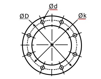
Ø D = Diameter
Ø k = Centre Diameter
n = Number of Holes
Ø d = Hole Diameter
|
ANSI (ASA) B 16,5 |
|
Inch |
150 psi |
300 psi |
||||||
|
Ø D |
Ø k |
n |
Ø d |
Ø D |
Ø k |
n |
Ø d |
|
|
¾" |
mm |
98,4 |
69,8 |
4 |
15,9 |
117,5 |
82,5 |
4 |
19 |
|
inch |
3⅞ |
2¾ |
⅝ |
4⅝ |
3¼ |
¾ |
|||
|
1" |
mm |
107,7 |
79,4 |
4 |
15,9 |
123,8 |
88,9 |
4 |
19 |
|
inch |
4¼ |
3⅛ |
⅝ |
4⅞ |
3½ |
¾ |
|||
|
1¾" |
mm |
117,5 |
88,9 |
4 |
15,9 |
133,3 |
98,4 |
4 |
19 |
|
inch |
4⅝ |
3½ |
⅝ |
5¼ |
3⅞ |
¾ |
|||
|
1½" |
mm |
127 |
98,4 |
4 |
15,9 |
155,6 |
114,3 |
4 |
22,2 |
|
inch |
5 |
3⅞ |
⅝ |
6⅛ |
4½ |
⅞ |
|||
|
2" |
mm |
152,4 |
120,6 |
4 |
19 |
165,1 |
127 |
8 |
19 |
|
inch |
6 |
4¾ |
¾ |
6½ |
5 |
¾ |
|||
|
2½" |
mm |
177,8 |
139,7 |
4 |
19 |
190,5 |
149,2 |
8 |
22,2 |
|
inch |
7 |
5½ |
¾ |
7½ |
5⅞ |
⅞ |
|||
|
3" |
mm |
190,5 |
152,4 |
4 |
19 |
209,5 |
168,3 |
8 |
22,2 |
|
inch |
7½ |
6 |
¾ |
8¼ |
6⅝ |
⅞ |
|||
|
4" |
mm |
228,5 |
190,5 |
8 |
19 |
254 |
200 |
8 |
22,2 |
|
inch |
9 |
7½ |
¾ |
10 |
7⅞ |
⅞ |
|||
|
5" |
mm |
254 |
215,9 |
8 |
22,2 |
279,4 |
234,9 |
8 |
22,2 |
|
inch |
10 |
8½ |
⅞ |
11 |
9¼ |
⅞ |
|||
|
6" |
mm |
279,4 |
241,3 |
8 |
22,2 |
317,5 |
269,9 |
12 |
22,2 |
|
inch |
11 |
9½ |
⅞ |
12½ |
10⅝ |
⅞ |
|||
|
8" |
mm |
342,9 |
298,4 |
8 |
22,2 |
381 |
330,2 |
12 |
25,4 |
|
inch |
13½ |
11¾ |
⅞ |
15 |
13 |
1 |
|||
|
10" |
mm |
406,4 |
361,9 |
12 |
25,4 |
444,5 |
387,3 |
16 |
28,6 |
|
inch |
16 |
14¼ |
1 |
17½ |
15¼ |
1⅛ |
|||
|
12" |
mm |
482,6 |
431,8 |
12 |
25,4 |
520,7 |
450,8 |
16 |
31,7 |
|
inch |
19 |
17 |
1 |
20½ |
17¾ |
1¼ |
|
DIN 28459 |
|
|
DN |
Ø D |
Ø k |
n |
Ø d |
|
TW 1 |
50 |
mm |
154 |
130 |
8 |
11 |
|
inch |
6.06 |
5.12 |
0.43 |
|||
|
TW 1 |
80 |
mm |
154 |
130 |
8 |
11 |
|
inch |
6.06 |
5.12 |
0.43 |
|||
|
TW 3 |
100 |
mm |
174 |
150 |
8 |
14 |
|
inch |
6.85 |
5.91 |
0.55 |
|||
|
TW 5 |
125 |
mm |
204 |
176 |
8 |
14 |
|
inch |
8.03 |
6.93 |
0.55 |
|||
|
TW 7 |
150 |
mm |
240 |
210 |
12 |
14 |
|
inch |
9.45 |
8.27 |
0.55 |
|
T.T.M.A |
|
Inch |
Ø D |
Ø k |
n |
Ø d |
|
2" |
mm |
114,3 |
95,3 |
6 |
11,1 |
|
inch |
4.50 |
3.75 |
0.44 |
||
|
3" |
mm |
142,9 |
123,8 |
8 |
11,1 |
|
inch |
5.63 |
4.87 |
0.44 |
||
|
4" |
mm |
168,3 |
149,2 |
8 |
11,1 |
|
inch |
6.63 |
5.87 |
0.44 |
||
|
5" |
mm |
196,9 |
177,8 |
8 |
11,1 |
|
inch |
7.75 |
7.00 |
0.44 |
||
|
6" |
mm |
228,6 |
206,4 |
12 |
11,1 |
|
inch |
9.00 |
8.13 |
0.44 |
||
|
8" |
mm |
276,2 |
257,2 |
16 |
11,1 |
|
inch |
10.87 |
10.13 |
0.44 |
|
Weight ≈ kg |
Thread BSP |
Materials / Application |
Dimensions ≈ mm |
Mann Tek Code No. |
||
|
D |
d |
s |
||||
|
0,001 |
BSP ½" |
PTFE (Teflon®) white, massive continuously hard, universally resistant Teflon® is a registred trademark of DuPont |
20 |
13 |
2 |
On request |
|
0,001 |
BSP ¾" |
26 |
19 |
2 |
1498-06 |
|
|
0,002 |
BSP 1" |
33 |
24 |
2 |
1220-06 |
|
|
0,003 |
BSP 1¼" |
42 |
34 |
2 |
1536-06 |
|
|
0,003 |
BSP 1½" |
48 |
39 |
2 |
1196-06 |
|
|
0,004 |
BSP 2" |
60 |
49 |
2 |
1052-06 |
|
|
0,007 |
BSP 2½" |
76 |
63 |
2,5 |
1181-06 |
|
|
0,006 |
BSP 3" |
88 |
77 |
3 |
1110-06 |
|
|
0,009 |
BSP 4" |
114 |
100 |
3 |
1295-06 |
|
|
0,016 |
BSP 6" |
164 |
150 |
3 |
1963-06 |
|
|
0,001 |
BSP ½" |
Thermopac asbestos free, light, hard. Especially for hot oils and hot bitumen up to 250º C and for hot water and saturated steam up to 25 bar. |
20 |
13 |
2 |
On request |
|
0,001 |
BSP ¾" |
26 |
19 |
2 |
1498-25 |
|
|
0,002 |
BSP 1" |
33 |
24 |
2 |
1220-25 |
|
|
0,002 |
BSP 1¼" |
42 |
34 |
2 |
1536-25 |
|
|
0,003 |
BSP 1½" |
48 |
39 |
2 |
1196-25 |
|
|
0,004 |
BSP 2" |
60 |
49 |
2 |
1052-25 |
|
|
0,005 |
BSP 2½" |
76 |
63 |
3 |
1181-25 |
|
|
0,009 |
BSP 3" |
88 |
77 |
3 |
1110-25 |
|
|
0,013 |
BSP 4" |
114 |
100 |
3 |
1295-25 |
|
|
0,016 |
BSP 6" |
164 |
150 |
3 |
1963-25 |
|
|
0,001 |
BSP ½" |
FPM/FKM (Viton®) soft for aromatic hydrocarbons and hot oils. Viton® is a registred trademark of DuPont. |
20 |
13 |
2 |
On request |
|
0,001 |
BSP ¾" |
26 |
19 |
2 |
1498-01 |
|
|
0,002 |
BSP 1" |
33 |
24 |
2 |
1220-01 |
|
|
0,002 |
BSP 1¼" |
42 |
34 |
2 |
1536-01 |
|
|
0,003 |
BSP 1½" |
48 |
39 |
2 |
1196-01 |
|
|
0,004 |
BSP 2" |
60 |
49 |
2 |
1052-01 |
|
|
0,006 |
BSP 2½" |
76 |
63 |
3 |
1181-01 |
|
|
0,008 |
BSP 3" |
88 |
77 |
3 |
1110-01 |
|
|
0,014 |
BSP 4" |
114 |
100 |
3 |
1295-01 |
|
|
0,016 |
BSP 6" |
164 |
150 |
3 |
1963-01 |
|
|
0,001 |
BSP ¾" |
PUR (Polyurethane) Flat seals type of polyurethane, hightly resitant to abrasion, non-toxic. Shore hardness = 90°. For all petroleum based products and many solvents. Colour: Blue |
26 |
19 |
2 |
1498-09 |
|
0,001 |
BSP 1" |
33 |
24 |
2 |
1220-09 |
|
|
0,001 |
BSP 1¼" |
42 |
34 |
2 |
1536-09 |
|
|
0,002 |
BSP 1½ " |
48 |
39 |
2 |
1196-09 |
|
|
0,003 |
BSP 1¾" |
54 |
44 |
2,5 |
On request |
|
|
0,003 |
BSP 2" |
60 |
49 |
2 |
1052-09 |
|
|
0,005 |
BSP 2½ " |
76 |
63 |
2,5 |
1181-09 |
|
|
0,006 |
BSP 3" |
88 |
77 |
3 |
1110-09 |
|
|
0,010 |
BSP 3½" |
100 |
80 |
3 |
On request |
|
|
0,009 |
BSP 4" |
114 |
100 |
3 |
1295-09 |
|
|
0,012 |
BSP 5" (No std.) |
140 |
124 |
3 |
On request |
|
|
0,016 |
BSP 6" |
164 |
150 |
3 |
1963-09 |
|
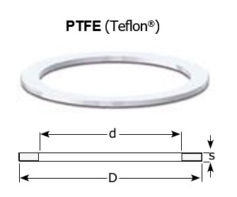
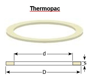
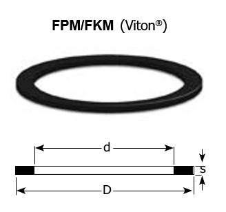
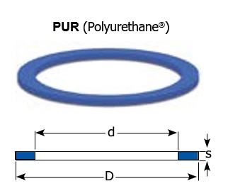
Viton® and Teflon® are registred trademarks of DuPont, DuPont Elastomers.
|
Designation |
Trade name |
ISO 1629 |
ASTM 1418 |
Temp. Range °C |
Field of Application |
|
|
Nitrile Butadiene Rubber / Nitrile Rubber |
Buna N® Europrene N® Hycar® Nipol N® Perbunan ® |
NBR |
NBR |
-55 |
110 |
Petroleum based products / aliphatic hydrocarbons (gasoline, diesel, oils, petroleum, propane, butane). Animal and vegetal oils and fats. Flame retardant liquids.. Silicone oils and greases. Water up to 80º C. |
|
Ethylene-Propylene Diene Rubber |
Dutral Keltan® Vistalon® Buna AP® |
EPDM |
EPDM |
-55 |
120 |
Water, hot water, vapour, brake fluids, detergents. Alcohols, ketons, engine coolants, phosphate based flame retardants, organic and inorganic acids and alkalis. Not suitable for petroleum based products. |
|
Fluoroelastomer |
Fluorel® Technoflon® Viton® |
FPM |
FKM |
-20 |
200 |
Petroleum based products / aliphatic hydrocarbons (gasoline, diesel, oils, petroleum, propane, butane) - also with high additive content. Phosphate based flame retardants. Silicone oils and greases, acids and alkalis. |
|
Fluorosilicone Elastomer |
–––– |
MFQ |
FVMQ |
-60 |
200 |
Additional to the properties of silicone elastomers, fluorosili- cone elastomers show a consideably higher resistance to oils, fuels and solvents - especially to aromatic and aromatic and chlorinated hydrocarbons and alcohols. |
|
Silicone |
Silastic® Silopren® |
MVQ |
VMQ |
-60 |
200 |
Very good heat and cold resistance, very good resistance to oxygene, ozone, UV rays and wheather influence. High electrical insulating properties, physiologically safe. |
|
Hydrogenated Nitrile Butadiene Rubber |
Therban® Tornac® Zetpol® |
HNBR |
HNBR |
-35 |
120 |
Very good resistance to petroleum based products / aliphatic hydrocarbons like NBR, but better resistance to high temperature, ageing and wheather influence. Excellent physical properties also with high temperatures. |
|
Butyl Rubber |
Exxon Butyl® Polysar Butyl® |
IIR |
IIR |
-55 |
100 |
For O-Rings this material has largely been replaced by EPDM. Butyl is resistant to the same fluid types as EPDM and -except for resistance to gas permeation- it is somewhat inferior to EPDM for O-Ring use. Excellent weather resistance and gas permeation resistance. Not suitable for petroleum based products. |
|
Perfluorinated Elastomer |
CHEMRAZ® Kalrez® PERLAST® |
FFPM |
FFPM |
-40 |
260 |
Best chemical resistance of all elastomers, including organic acids, acetic acid, benzoic acid, formic acid. |
|
Chloroprene Rubber |
Baypren® Neoprene® |
CR |
CR |
-40 |
120 |
Resistant to refrigerants, ammonia, carbon dioxide, freon (R12, R13, R21, R22, R113 - R115), silicone oils, water, oxygen (low pressure), alkalis, coustic soda, alcohols, chlorine, ozone, castor oil and vegetable oils. Properties of CR are similar to NBR but slightly lower resistance to petroleum based producs, better resistance to ageing, UV light and ozone. |
|
Polyester / Polyether Urethane Rubber |
Polyurethane Adiprene® Urepan® Desmopan® |
PU PUR AU EU |
AU EU |
-40 |
100 |
Very good resistance to petroleum based products, also with aromatic content. Good resistance to ozone and ageing. Very good mechanical properties. Not resistant to esters, concentrated acids and lyes, water above +50º C. |
|
Polytetrafluoroethylene |
Teflon® |
PTFE |
PTFE |
-200 |
260 |
Universal chemical resistance except liquid alkaline metals and some fluorine compounds. Very good anti friction properties, low wear. High tempera- ture resistance. Physiologically safe. Use for statical seals only. |
|
Fluorinated Ethylene Propylene |
Teflon FEP® |
FEP/MVQ |
FEP/VMQ |
-60 |
200 |
Universal chemical resistance except liquid alkaline metals and some fluorine compounds. Very good anti friction properties, low wear. High tempera- ture resistance. Physiologically safe. |
|
FEP/FPM |
FEP/FKM |
-20 |
200 |
|||
|
Perflouralkoxy |
Teflon PFA® |
PFA/MVQ |
PFA/VMQ |
-60 |
250 |
Universal chemical resistance except liquid alkaline metals and some fluorine compounds. Very good anti friction properties, low wear. High tempera- ture resistance. Physiologically safe. |
|
PFA/FPM |
PFA/FKM |
-20 |
250 |
|||
|
Tetrafluoroethylene- Propylene Copolymer Elastomer |
Aflas® |
–––– |
TFE / P |
-25 |
200 |
Petroleum based products, oils and greases, brake fluids, fuels, alcohols, heat transfer media, oils. amines, acids, al- kalis. |
Note: Specifications in this chart are based on the information given by our suppliers together with published guides. This is not always a guarantee for a proper function. If in doubt, please ask our sales team, statiing medium and operating conditions.
Please observe the following basic rules :
Note: When this procedure is done, the connection becomes permanent. Extreme measures will be necessary to disconnect these components. All other measures to seal the threads should be explored prior to use of this technique.
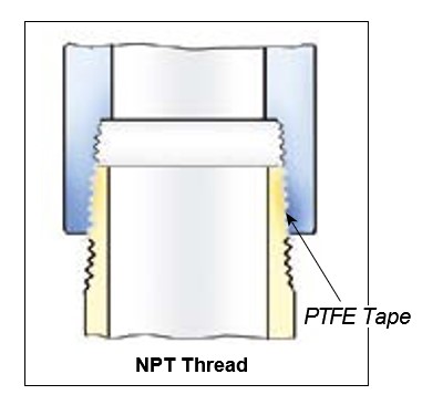
Couplings with conical (tapered) female and male threads normally have no flat sealing surface. The screwed-on thread jams before the end of the counter thread is covered. Therefore a sealing with a thread seal is not possible. The overall length of such a connection is always longer than the equivalent flat sealing system. A safe and promptly tight connection requires expert knowledge and clean work and is time-consuming. Subsequent tightening during operation is not possible. A new assembly requires the proper cleaning of the pitch from all squashed and hardenedremains of the sealing compounds.
For these reasons, BSP parallel threads should be preferred.
Easy sealing with flat thread seals :
Standard hose fittings are supplied with parallel threads and a flat sealing surface. This allows to use the full thread length for screwed-on parts. Due to the short length, a good transfer of force is guaranteed.
The thread seal is positioned within a recess of the female part and can not fall out. For a safe connection, the parts simply have to be screwed together – subsequent tightening during operation is possible at any time. A change of seals or reassembly do not require any expert knowledge. The European standardisations for hose assemblies require parallel threads with flat seals, because of these advantages.
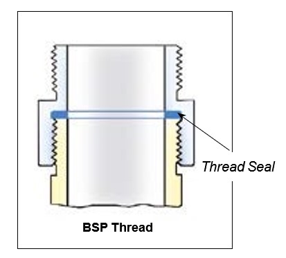
This advice is supplementary to your standard terminal operational procedures.
DACouplings, DDCouplings and DG- Couplings are specifically designed for the bulk transfer of liquids and vapours. The materials of construction, including the seals should already be confirmed as compatible prior to installation. If in doubt, check before operation. Our help documents "Installation advice for DA- Couplings, DDCouplings and DGCou- plings" plus "Specification Advice" are designed to assist you.
All DACouplings, DDCouplings and DG- Couplings are marked with a maximum pressure rating that shall not to be ex- ceeded. With careful use and regular maintenance they will give safe and trou- ble free operating for many years.
Service instructions are available for all DACouplings, DDCouplings and DGCou- plings upon request. The life expectancy and maintenance frequency of the coup- lings is dependent upon many variables such as cycles/day, pressures, contami- nates etc., but the most significant factor besides correct installation is the correct use. The following information is desig- ned to assist in your care of the coup- lings and associated equipment.
Daily visual inspection
All hose units should be briefly inspected at the start of each day’s operation. Look inside the connection socket. Check that the three rollers are not obviously dama- ged. Check that the connection socket area is free from dirt and foreign objects.
Check for signs of seal damage (eg. you may see a cut seal or small pieces of rubber coming from the piston area).
Check that the swivel of the hose unit ro- tates freely. For the first use, check for leakage and smooth coupling operation.
Each tank unit on the truck should also be briefly checked prior to use. Check for dirt, tightness and any obvious physical damage.
Connecting & disconnecting
At the completion of the 100 degree turn you will feel a definite stop. Do not att- empt to rotate the unit further. Further rotation does not tighten the connection or open the valves more, it only cause unnecessary damage. Hose and tank unit valves are now open and the loading process can start.
We recommend the use of dust plugs /caps.
Daily inspection:
All DACouplings, DDCouplings and DG- Couplings are designed for trouble free operation in a wide range of applications and operating conditions. Reliable and safe operation is dependent upon the correct installation and hand- ling of the equipment. Regular and appropriate maintenance is essential to ensure both safety and relia- bility over the life of the equipment.
Specifications
Before you install Mann Tek couplings, it is essential to check that the material and performance specifications are ac- ceptable for your specific application. The pressure ratings and primary ma- terials of the construction are clearly in- dicated on the identification tag of each Mann Tek product. A drawing showing the materials of construction relating to each individual component is available upon request. If required, the technical department at Mann Tek will provide guidance on material suitability. Our data is taken from published chemical resis- tance information as well as our own ap- plication experiences. Specification checks should always be carried out before the product is sup- plied, but if unsure, please ask. Espe- cially if you are using the couplings out- side the standard temperature range (- 20º C to + 80º C), ask for confirmation regarding your application. Do not assume that a Mann Tek coup- ling supplied for one specific application automatically will be suitable for other si- milar applications. Many variables affect the performance of materials. If you wish to use a DACoup- ling, DDCoupling or DGCoupling for a dif- ferent application than the one originally specified, check with Mann Tek to ensure compatibility before installation. Please remember, the application details should include all media transferred through the coupling, not just the primary transferred media. As with all equipment, a check should be made to ensure that the installation fulfils the requirements of applicable prevailing industry, local, national and international standards. Particular attention should be paid to pressure ratings, safety factors and the position of upstream and downstream affiliated closures.
Installation
The correct installation of Mann Tek Couplings is essential to ensure safe and satisfactory operation. Checks should be made to ensure that their installation does not interfere with the correct opera- tion of affiliated equipment (i. e. isolation valve, excess flow valves, etc).
Before securing the flange or thread connection to the mating equipment (i. e. hose, loading arm, storage tank) ensure that no dirt or foreign objects are present in the coupling. All flange and thread connections should be made without ex- cessive strain to the equipment. Prior to use they should be pressure checked at least to 1.5 times of the maximum appli- cation working pressure. All gaskets and sealing materials used to make the per- manent connection should be of suitable material and able to operate at least up to the maximum parameters of the Mann Tek coupling. When installing DACouplings, DDCou- plings and DGCouplings to new pipe work, tanks etc. ensure the system is free from debris that may be transferred through the coupling. Where the hose or loading arm assembly is the primary static dissipation or earth route, the electrical continuity value of the assembly shall be checked to ensure regulatory compliance. Special attention should be paid to the balancing of loading arms. The weight of the coupling plus transfer media should be taken into account at the specification stage. It is usual for loading arm balance settings to account of weight variations due to differences in the full / empty cyc- le. The loading arm should be set to ba- lance in the condition present at the time or connection. For example, should the loading arm be empty at the time of con- nection then it should be balanced in the empty condition. Each DACoupling, DDCoupling and DG- Coupling is designed to take reasonable loads associated with good handling practice but is not designed to accept continuous excessive loads associated with maladjustment or poor installation. Continuous excessive strain will lead to increased component wear and, if no actions will be taken, damaging the coupling and adjacent units up to failure of the connection. This means, under circumstances, high follow-up costs for environmental and personal injuries.
When Mann Tek couplings are used with hoses, attention should be paid to hose length to ensure correct handling cha- racteristics. The hose assembly should be designed such that the hose weight is supported by the coupling or the opera- tor. Hoses should have a sufficient length to ensure operation well within the sti- pulated hose minimum bending radius. It is recommended to apply Safety Break-Away Couplings to protect the whole loading equipment against unin- tended external forces, e. g. caused by a drive-away accident. Further, measu- res against electrostatic loads are nee- ded, especially at higher flow velocities (above approx. 5 m/s for fuels). Prior to putting the system in use, a func- tion check should be carried out. The hose unit (coupler) should connect and disconnect without physical interference or difficulty. Please note – the higher the static pressure, the greater the effort to make a connection. For more details ple- ase read the 'Operating Advice for Mann Tek Couplings'.
Maintenance
All DACouplings, DDCouplings and DG- Couplings should be visually checked for damage, etc. on a daily or shift basis according to the handling instructions. Any sign of damage or operating difficul- ty should be reported and acted upon at the earliest opportunity. Do not continue to use any equipment that is not opera- ting satisfactorily as continued use will cause further deterioration and possible equipment failure. Mann Tek couplings are designed such that all normal wear parts are included in appropriate maintenance kits. For nor- mal applications, where the material is not, or only marginally attacked by the medium, the coupling will be fully usable after the regular maintenance.
We recommend that the coupling is fully inspected, tested and serviced at least once a year. It must be accepted that some applications cause a greater le- vel of component degradation either by chemical attack or by arduous physical or environmental conditions. In such cir- cumstances a more frequent regime of inspection and service may be required. We recommend that in such applications a three monthly inspection should be carried out with automatic replacement of the hose unit piston and carrier seals. All other service parts and key compo- nents should also be checked. In addi- tion to the three monthly inspection and primary seal replacement, the hose unit shall have the full repair kit applied every year independent from component con- dition. After a representative period of time it may be possible to increase the service / inspection interval, but only against a background of satisfactory operation.
Full service instructions complete with photographs are available for each DA- Coupling, DDCoupling and DGCoupling size. These instructions show the service method as well as tools required and parts identification. DACouplings, DD- Couplings and DGCouplings are easy to maintain. Some Mann Tek distributors are trained and accredited by Mann Tek to carry out service of Mann Tek couplings. Alterna- tively, Mann Tek offers a maintenance and repair service in their workshop. A service training can be offered as well, either on or off site to customers engi- neers who wish to carry out servicing themselves. Mann Tek equipment should only be ser- viced by trained personnel. The distributor of Mann Tek couplings has full responsibility to enclose this information to the customer. If the cus- tomer does not understand English the Distributor also have the responsibility to translate this document to a language the customer fully understand.
Test method to STANAG 3756, Annex E
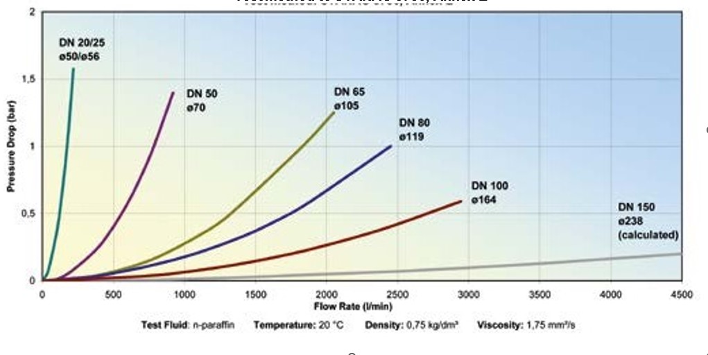
Test method to STANAG 3756, Annex E
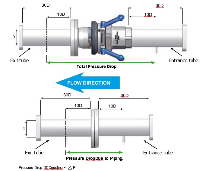
Pressure Drop Mann Tek DDCoupling = Total Pressure Drop - Pressure Drop Due to Piping
Repair Service
To comply with Health & Safety Regulations, all returned couplings and valves must be accompanied by a Certificate of Cleanliness and a data sheet for the last product carried (also for the cleaning medium).
Certificate of Decontamination
We certify that the returned couplings/valves have been cleaned prior to despatch and are free of any harmful substances.
|
Quantity: |
|
Quantity: |
|
|
Code No.: |
|
Code No.: |
|
|
Serial No.: |
|
Serial No.: |
|
|
Quantity: |
|
Quantity: |
|
|
Code No.: |
|
Code No.: |
|
|
Serial No.: |
|
Serial No.: |
|
|
|
YES |
NO |
|
Free of all liquid |
|
|
|
Air blown |
|
|
|
Coupling / Valve dismantled |
|
|
The last known product the coupling / valve was in contact with:
Company Name / Adress
EU / CAS / UN Number: Signature of Supervisor:
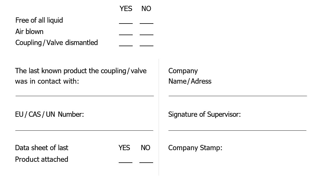
When sending used couplings or valves to Mann Tek, please fill in this form and enclose it to the attach to the shipment.
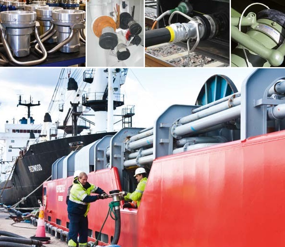
Didn't find the right Dry Disconnect Couplings?
Fill in the form below, and we'll assist you further!
Curious about our blog? Check out all our items here!
Contact us here


 Nederlands
  Deutsch